I have customized a 3D robot in the animation module. The general robot shape and the axes are almost okay. But there is an issue: when I play and reset the simulation, the robot changes its shape automatically. I would like to use it as a pick-and-place robot. Could anyone help me solve this issue? The robot file has been uploaded. Thank you very much!robotmodel.7z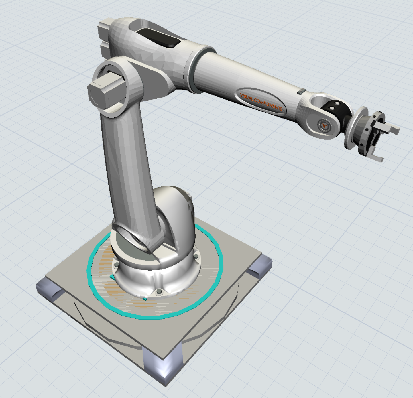
Customized 3D robot issue
FlexSim 24.0.0
I created my robot based on this video. However, I still meet this issue. Could anyone solve it based on my files? Many thanks!
Hi @royjuventus29, was Joerg Vogel's answer helpful? If so, please click the "Accept" button at the bottom of their answer. Or if you still have questions, add a comment and we'll continue the conversation.
If we haven't heard back from you within 3 business days we'll auto-accept an answer, but you can always comment back to reopen your question.
@royjuventus29, I adjusted by dragging or editing values of each component in Animation Editor and then I saved for this component its Base Position. 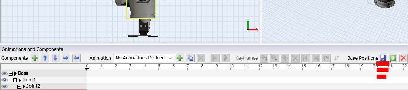
It is not the problem of saving Base Position. I already did it.
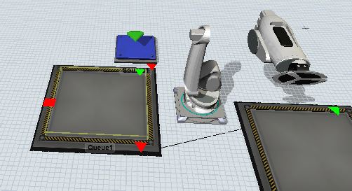
@royjuventus29, I decomposed your model a bit. There are now more gaps. But I achieved this in the way I described it above:
@royjuventus29 , added component consists as every other object of size, rotation and location values in a matrix. This is the yellow bounding box of an highlighted object or selected as a red bounding box. BUT an object consists also of a shape. And this shape offset factors can you edit in quick properties panel in visuals under more visuals. I tried this and I succeeded by adjusting shape factors in more visuals. I saved the model, opened it again and hit reset. And the shape keeps its size.
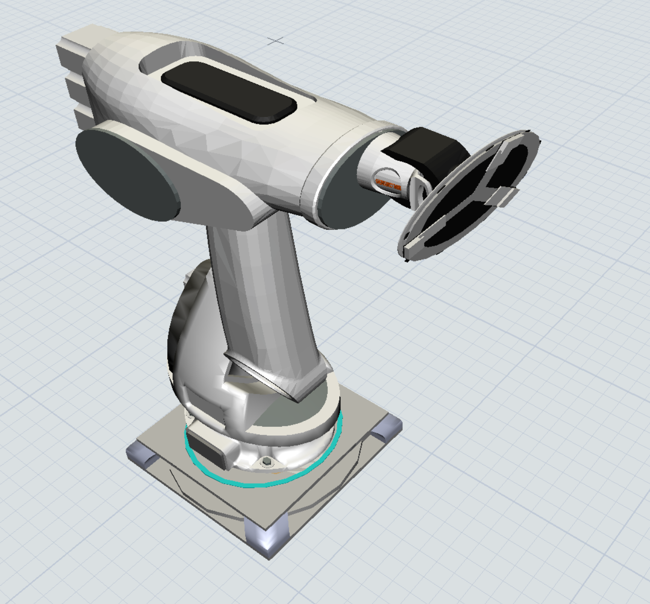
Can you change the Base and Joint 1 back to their original positions, as I showed in the first picture? When we play the simulation these joints change 90 degrees immediately. I don't want this to happen.

16 People are following this question.