question

niko J2 avatar image
0 Likes"
niko J2 asked Phil BoBo commented

How to change direction of Conveyor Drawing function_s

Hello,

i would like to automatize Conveyor building via CAD Data.

Straight conveyor are working pretty well.

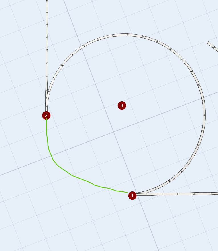
My CAD data for curved conveyor are like:

startpoint (1), endpoint (2) & mid of circle (3).

im using these commands

function_s(newConveyor, "dragStart", xKoordSt, yKoordSt, zKoordSt, activedocumentview());

function_s(newConveyor, "dragEnd", xKoordEn, yKoordEn, zKoordEn, activedocumentview());

how to change direction of conveor (green line)

Choose One
conveyorsconveyor moduleautobuildconveyor properties
o582d.png (81.0 KiB)
5 |100000

Up to 12 attachments (including images) can be used with a maximum of 23.8 MiB each and 47.7 MiB total.

1 Answer

·
Phil BoBo avatar image
1 Like"
Phil BoBo answered Phil BoBo commented

Rather than using dragStart and dragEnd function_s commands, you can set the values of the curved conveyor directly, such as the code below.

A curved conveyor is specified in FlexSim via the location (mid of circle), start angle, sweep angle, and radius.

Object dwg = model().find("FlexsimModelBackground");
Table vertexLocations = getvarnode(dwg, "snapPoints").subnodes["Vertex Locations"];
Table lines = getvarnode(dwg, "snapPoints").subnodes["Lines"];
Table arcs = getvarnode(dwg, "snapPoints").subnodes["Arcs"];

treenode LibraryCurvedConveyor = node("?CurvedConveyor", library());
for(int j = 1; j <= arcs.numRows; j++) 
{ 
	int startIndex = arcs[j][1] + 1; 
	double x1 = vertexLocations[startIndex][1]; 
	double y1 = vertexLocations[startIndex][2]; 
	double z1 = vertexLocations[startIndex][3]; 
	int endIndex = arcs[j][2] + 1; 
	double x2 = vertexLocations[endIndex][1];
	double y2 = vertexLocations[endIndex][2]; 
	double z2 = vertexLocations[endIndex][3]; 
	int centerIndex = arcs[j][3] + 1;
	double x3 = vertexLocations[centerIndex][1];
	double y3 = vertexLocations[centerIndex][2]; 
	double z3 = vertexLocations[centerIndex][3]; 
	double StartAngle = Math.degrees(arcs[j][4]); 
	double EndAngle = Math.degrees(arcs[j][5]);
	double SweepAngle = EndAngle - StartAngle;
	if (SweepAngle < 0) {
		SweepAngle += 360;
	}

	Conveyor curved_conveyor = createinstance(LibraryCurvedConveyor, model()); 
	curved_conveyor.setLocation(x3,y3,z3);
	
	double dx = x3 - x1; 
	double dy = y3 - y1; 
	double dz = z3 - z1; 
	double radius = sqrt(dx*dx + dy*dy); 
	 
	setvarnum(curved_conveyor, "rise", dz);
	setvarnum(curved_conveyor, "startAngle", StartAngle);
	setvarnum(curved_conveyor, "sweepAngle", SweepAngle);
	setvarnum(curved_conveyor, "radius", radius);

	function_s(curved_conveyor,"finalizeSpatialChanges");
}
· 4
5 |100000

Up to 12 attachments (including images) can be used with a maximum of 23.8 MiB each and 47.7 MiB total.

niko J2 avatar image niko J2 commented ·

Thanks for the answer.

the orientation of the conveyors are stil a false. But i can fix that.

another problem is that i cant rotate curved conveyors.

I want the conveyor to pass the blue line.

0 Likes 0 ·
oqumu.png (3.5 KiB)
Phil BoBo avatar image Phil BoBo ♦♦ niko J2 commented ·

You rotate curved conveyors by changing the startAngle.

I don't understand what you mean by "pass the blue line."

0 Likes 0 ·
niko J2 avatar image niko J2 Phil BoBo ♦♦ commented ·

By changing the startAngle I can just rotate around the z-axis.

Is it possible to "twirl" the conveyor or rotate around y/x axis?

The blue Line has higher z coordinate in the mid.

0 Likes 0 ·
0rmsz.png (5.8 KiB)
Show more comments

Write an Answer

Hint: Notify or tag a user in this post by typing @username.

Up to 12 attachments (including images) can be used with a maximum of 23.8 MiB each and 47.7 MiB total.