Generally, the 3D library objects in FlexSim have a "left-to-right" flow, in the default view of them. For example, the processor Input ports start at its upper left corner, the output ports start at the upper right corner. Same for planes and pretty much all the other 3D library objects. However, when there's a simulation with a generally right-to-left flow (i.e. the opposite way), I'd like to flip-flop the input/output port locations so things general flow from right to left (rather than have In/Out connectors that criss-cross each other). One way to do that of course, is to change each object's Z rotation from 0.0 to 180.0, which flips it upside down. However, seems it would be cleaner if I could just change the port locations (or better yet, change the default port locations in the library objects, if I anticipate most of my 3D layout flow will be primarily right-to-left). I did check the Tree view under "spatial" and "connections" but did not find where I could change these port "anchor" locations.
question
Change locations of input and output ports on objects?
1 Answer
Hi @Mike Mayer
The arrows are just indicative of which way the flow is going. Currently there is not a way to move the connection arrows. Like you said, you can rotate the objects 180 degrees or I'd recommend hiding the arrows by going into Presentation Mode under View Settings in the Quick Properties or unchecking the Show Connections box.
Thanks Isaac. My goal is to show movement of items between objects as well, so I may actually wind up with conveyors, which are an easy way to simulate travel delay (as the crow flies) and at the same time allow the eye to follow objects through the model in a simple way. For that, I will likely disable the arrows and connections, so that only the "conveyors for the purposes of the travel delay" are visible, and as such, can be pretty much be placed wherever I need to in order to indicate a desired flow direction. Another thought, as a product enhancement, are that the connectors as-is are, in a way, a "zero-time" transport. An interesting enhancement to them would be the ability to assign a travel time to them, so in essence they become more-or-less a simple no-frills "zip line" between objects, if it's desired to show movement over time (versus objects hopping invisibly from one object to another, in zero time). Of course, conveyors can aptly accomplish this too, and can be made visually thin.
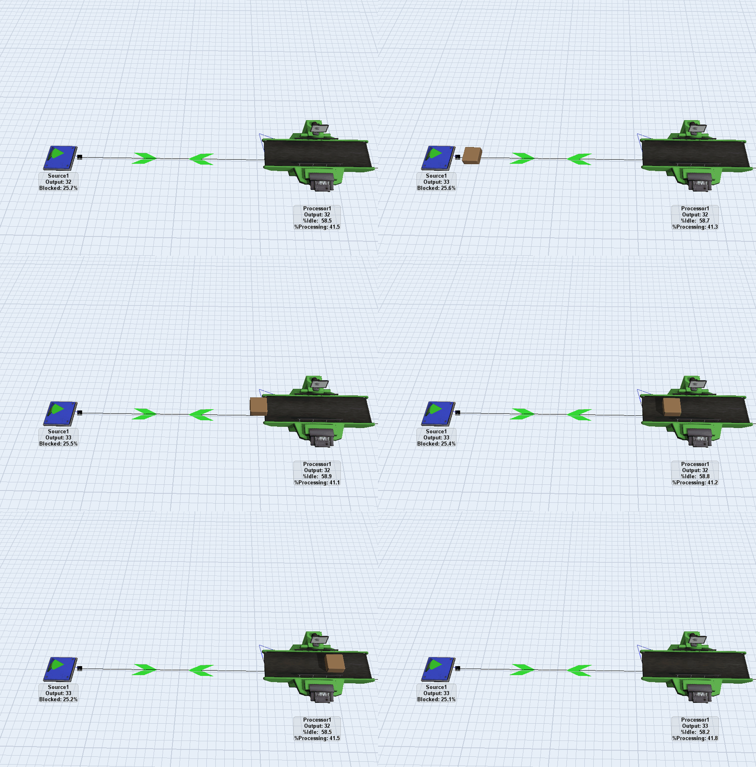
Is this similar to the visual you are trying to achieve?
Conveyors would work as well.
Yes Isaac, that's it. I see you used network nodes and connectors between them. Since there's no explicit transporter to move the brown box flowitem (like a person, or a forklift), did you make the brown box flowitem a Task Executer Flow Item? I.e., an transporter that moves itself? Clever.
The movement of items had been a feature of the deprecated flownode objects. You can post an idea to get them back into library of the 3D objects.
Jorg,
Thanks for the reminder - I was trying to think of the name of that depricated feature - "flownodes". I discovered that feature accidentally a few years ago, and started playing with it. It was pretty interesting although I found a few times it didn't work quite as expected. Nonetheless, I did build a working model using flownodes as a way to visually represent movement between functional areas. Process Flow as well as other techniques has eclipsed flownodes, however I wouldn't mind taking another look at them.
question details
8 People are following this question.
