Example Usage of the New AutoCAD FlexScript API
The following example models were demonstrated at the Autodesk University presentation Elevating Factory Design: FlexSim and the Future of Autodesk Fusion Digital Factory. Refer to that presentation for a demo of these models and additional discussion regarding the topics demonstrated by these examples.
These examples require the Autodesk Interop FlexSim Module.
Healthcare Auto-Build Example
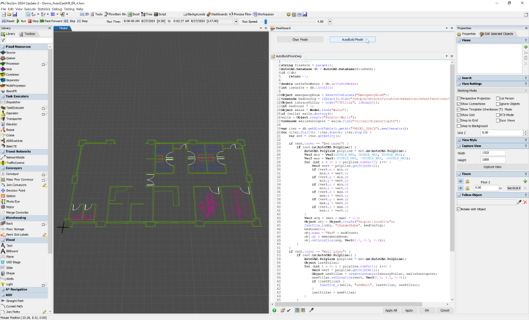
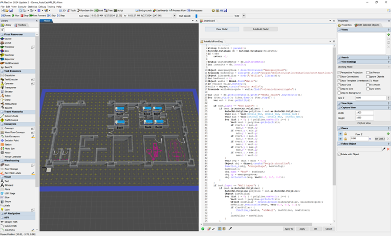
Using the new AutoCAD FlexScript API, the data within dwg files can be read using FlexScript to automatically build simulation objects within the model.
The script in this Healthcare example is contained in the AutoBuildFromDwg() user command in the Toolbox. This command reads the average location of blocks on the Bed Layer to create Bed Location objects. It also reads the lines on the Wall Layer to automatically create Wall objects and connect them to the A* Navigator for automatic pathfinding around the walls.
Reading dwg data
- string filePath = param(1);
- AutoCAD.Database db = AutoCAD.Database(filePath);
- if (!db)
- return -1;
- var iter = db.getBlockTable().getAt("*MODEL_SPACE").newIterator();
- for (iter.start(); !iter.done(); iter.step()) {
- var ent = iter.getEntity();
- print("Entity:", ent.layer, ent.objectType);
- if (ent.layer == "Bed Layer") {
- if (ent.is(AutoCAD.Polyline)) {
- AutoCAD.Polyline polyline = ent.as(AutoCAD.Polyline);
- }
- }
- }
Creating a bed location
- treenode bedConfig = library().find("/people/Objects/Location>behaviour/eventfunctions/configs/Bed");
- Object obj = Object.create("People::Location");
- function_s(obj, "changeShape", bedConfig);
Creating walls
- Object walls = Model.find("Walls");
- if (walls) walls.destroy();
- walls = Object.create("People::Walls");
- treenode wallsSurrogate = walls.find(">visual/drawsurrogate");
- Object libraryPillar = node("/?Pillar", library());
- Object newPillar1 = createinstance(libraryPillar, wallsSurrogate);
- newPillar1.setLocation(0.0, 0.0, 0.0);
- Object newPillar2 = createinstance(libraryPillar, wallsSurrogate);
- newPillar2.setLocation(10.0, 0.0, 0.0);
- function_s(walls, "addWall", newPillar1, newPillar2);
Asserting the A* Navigator, a Grid, and connecting Walls
- Object walls = Model.find("Walls");
- Object aStarNavigator = model().find("AStarNavigator");
- if (!aStarNavigator) {
- aStarNavigator = createinstance(library().find("?AStarNavigator"), model());
- }
- Object grid = aStarNavigator.find("Grid1");
- if (!grid) {
- grid = function_s(aStarNavigator, "createGrid", 0, 0, 0, 1, 1, 0);
- grid.name = "Grid1";
- }
- contextdragconnection(grid, walls, "A");
AGV Read/Write Dynamic Blocks Example
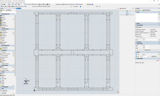
POC_OHT_3_MoveOHB.dwg (If this file is named differently when you download it from Answers, make sure you name it back to this exact name. It is referenced by name in the model.)
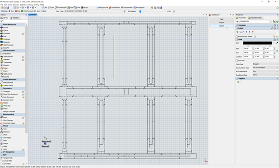
The script in this AGV example is contained in the interopAutoCAD() user command in the Toolbox. This command reads the location and names of particular dynamic blocks in the dwg file in order to automatically create AGV path simulation objects based on the configuration of each type of dynamic block.
Additionally, the script has examples of both reading data and writing data back to the dwg based on modifications of the AGV paths within the simulation. The script is only partially complete as a demonstration of the API’s capabilities; the script is not a fully-working, robust solution for any arbitrary dwg.
Factory Design Utilities Proof of Concept Example
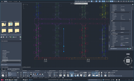
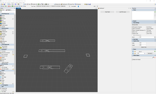
This FDU example model contains many user commands in the Toolbox with various functionality. The primary example starts in the Load FDU Layout button’s OnPress code. By default, it calls the AutoBuildFromDwg() user command. Alternatively, it has unreachable example code for calling AutoBuildFromLayout(), which can read the layout data from an FDU LayoutData xml file rather than a dwg file.
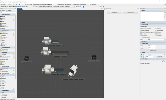
The AutoBuildFromDwg() user command reads factory-specific meta-data about each FDU block in the dwg file and automatically creates simulation objects for each. The simulation objects then load the custom 3D shapes from FDU representing each of those objects. The import script also sets labels with the various Factory properties from each object. Within the CreateSimulationObjects() and CreateInternalObjects() user commands—called from the CreateFactoryAssetInstance() command—are hard-coded checks for particularly factory asset family ids to determine what type of simulation objects to create. This is merely a proof-of-concept example for handling FDU assets via FlexScript without any changes to FDU assets themselves. Future enhancements may include options for including such simulation meta-data within FDU assets directly for a more robust, easier-to-use solution.
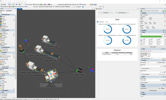
This workflow brings all the new Autodesk interop features together for an exciting, new way to bring factory data into FlexSim. Once that data is in FlexSim, you can use its many existing features to analyze the system with live 3D animation and dashboard charts showing simulation results. You can validate the throughput of the layout, identify potential bottlenecks, and balance resource use.

