One of the most powerful uses of a Fixed Resource Process Flow is to unify a set of machines and operators as a reusable entity. For example, many factories have several production lines. Simulation modelers often wonder what would happen if they could either open or close more production lines. If you were to open a new line, would the increased output be worth the cost? Or if you were to close a line, would the factory still be able to meet demand? These are the kinds of questions modelers often ask, and by using a Fixed Resource Process Flow, you can answer this question.
This article demonstrates how to use a Fixed Resource Process Flow (or FR Flow) to coordinate several machines and operators as a single entity. The example model represents a staging area, where product is staged before being loaded on to a truck. However, most of the concepts that are discussed could be used in any Fixed Resource Process Flow.
Creating a Collection of Objects
When you set out to build a reusable FR Flow, it is usually best to start by making a single instance of the entity you want to replicate. Often, it is convenient to build that entity on a Plane. When you drag an object in to a Plane, it is owned by the Plane, which makes the Plane a natural collection. If you copy and then paste the Plane, the copy will have all the same objects as the original Plane. This makes it very easy to make another instance of your entity: just copy and paste the first. If the Plane is attached to an FR Flow, then the copy will also be attached to the same Flow, and will then behave the exact same way.
In the example model, you will find a Plane with a processor, five queues, and two operators. This makes up a single staging area. The Plane itself is attached to the FR Flow, meaning an instance of the FR Flow will run for the Plane. It also means the Plane can be referenced by the value current. (You may find it helpful to set the reset position of any operators, especially if they wander off the plane at any point during the model run.)
Using Process Flow Variables
In order to drive the logic in your entity using an FR Flow, you will need to be able to reference the objects in each entity, so that they will be easily accessible by tokens. For example, if items are processed on Machine A, Machine B, and Machine C, in a production line, then you would want an easy way to reference those machines in each line.
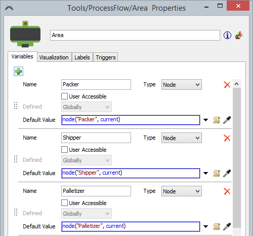
This is where Process Flow Variables come in. In the example model, you will find the following Process Flow Variables:
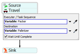
Every staging area has a Packer, a Shipper, and a Palletizer, each referenced using the node command. Remember that current is the instance object, which is the Plane. Once these variables are in place, you could create an FR Flow like the following:
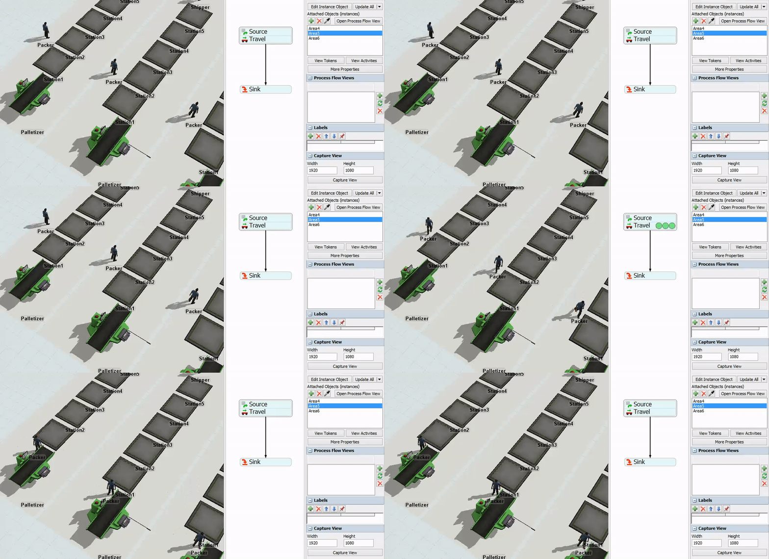
If you ran this model with the Plane shown previously (complete with correctly named objects) and this flow with the shown variables, then the Packer operator would travel to the Palletizer. If you then copied the Plane, you would see that all Packers go to their respective Palletizers, as shown below:
Using Variables and Resources Together
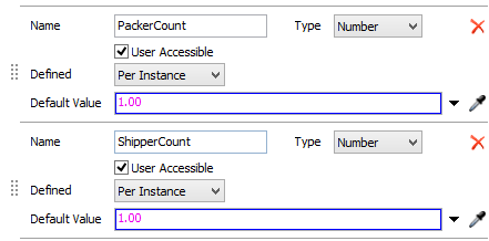
Sometimes, you may want to adjust the number of operators per line, or even the number of operators in a specific role. To do this, you can again you Process Flow Variables. The sample model includes these variables:
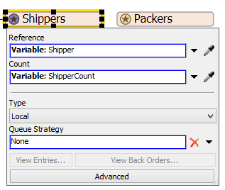
The sample model also includes these resources; the properties for the Shipper Resource are shown:
Because this resource is Local, it is as if each attached object has its own version of this resource. Because it references a 3D operator, it will make copies of that operator when the model resets. The number of copies it creates will depend on the local value of the ShipperCount variable. To edit the value for a particular instance object, click on that object in the 3D view, and edit the value in the quick properties window.
Disabling Entities
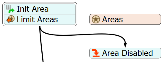
Often, modelers simply want to "turn off" parts of their model. If that part of the model is controlled by a fixed resource flow, then you can easily accomplish this task. In the example model, you will find the following set of activities:
The Areas resource is numeric, and it is global. The Limit Areas activity is configured so that any token that can't acquire the resource immediately goes to the Area Disabled sink. If the token that controls the process dies, then the area for that token is effectively disabled. The example model uses a Process Flow Variable to control how many areas can be active at a time:
The Areas resource uses this value to control how many shipping areas are actually active. If this number is smaller than the number of attached objects, then some of the areas won't run. Note that the order the objects are attached in matters. The first attached area will be the first to generate a token in the Init Area source, and so will be the first one to acquire the area.
Using Process Flow Variables in the Experimenter/Optimizer
Currently, only Global and User Accessible variables can be accessed in the Experimenter. In the sample model, the only variable that can readily be used in an experiment is the TotalAreas variable, which dictates how many areas can be active. This allows the Experimenter or Optimizer to disable lines.
To make it possible for the Experimenter or Optimizer to vary the number of Shippers or Packers per Area, the ShipperCount and PackerCount could be changed to Global Variables. You could put labels on the instance object (the Plane) that are read by the variable, like so:
Then the experimenter could set the label value on the Plane object that is attached to the FR Flow. The Experimenter would set the label, which would affect the value of the Variable, which would affect how many copies of the Packer were created by the Packer resource. You could do the same for the ShipperCount variable.
Sample Model
The attached model (usingfixedresources-6.fsm) provides a working model that can demonstrate the principles in this article. It comes with only one Plane object attached to the FR Flow. Here are some things to try with the model:
- Reset and run the model to see how it behaves with a single area, where that single area has only one Packer and one Shipper.
- Create a copy (use copy/paste) of the Plane. Reset and run the model again to see how a second area is automatically driven by the same flow. You may need to adjust the TotalAreas variable if the second doesn't run.
- Adjust the number of Packers and Shippers (using the Process Flow Variables) on each Plane. Reset and run the model to see how adding more packers and shippers affects it.
- Create many copies of the first Plane (it is best to set the PackerCount and ShipperCount to 1 before copying). Reset and run the model, to observe the effect.
- Add or remove some staging areas (queues) to an Area. This model handles those changes as well (in the Put Stations On List part of the flow).
- Try to set up an experiment or optimization, that varies how many lines are active, and how many Packers and Shippers are in each.
In general, play around with the sample model, or try this technique on your own.
Other Applications
This technique can be used to create production/packaging lines, complex machines, or any conglomerate of Fixed Resources and Task Executers. If you follow the methods outlined in this article, you will be able to create additional instances of complicated custom objects with ease. You will also be able to configure your model for use with the experimenter or optimizer.


