I don't know if this is an Autodesk Inventor issue, 3ds Max issue or FlexSim issue.
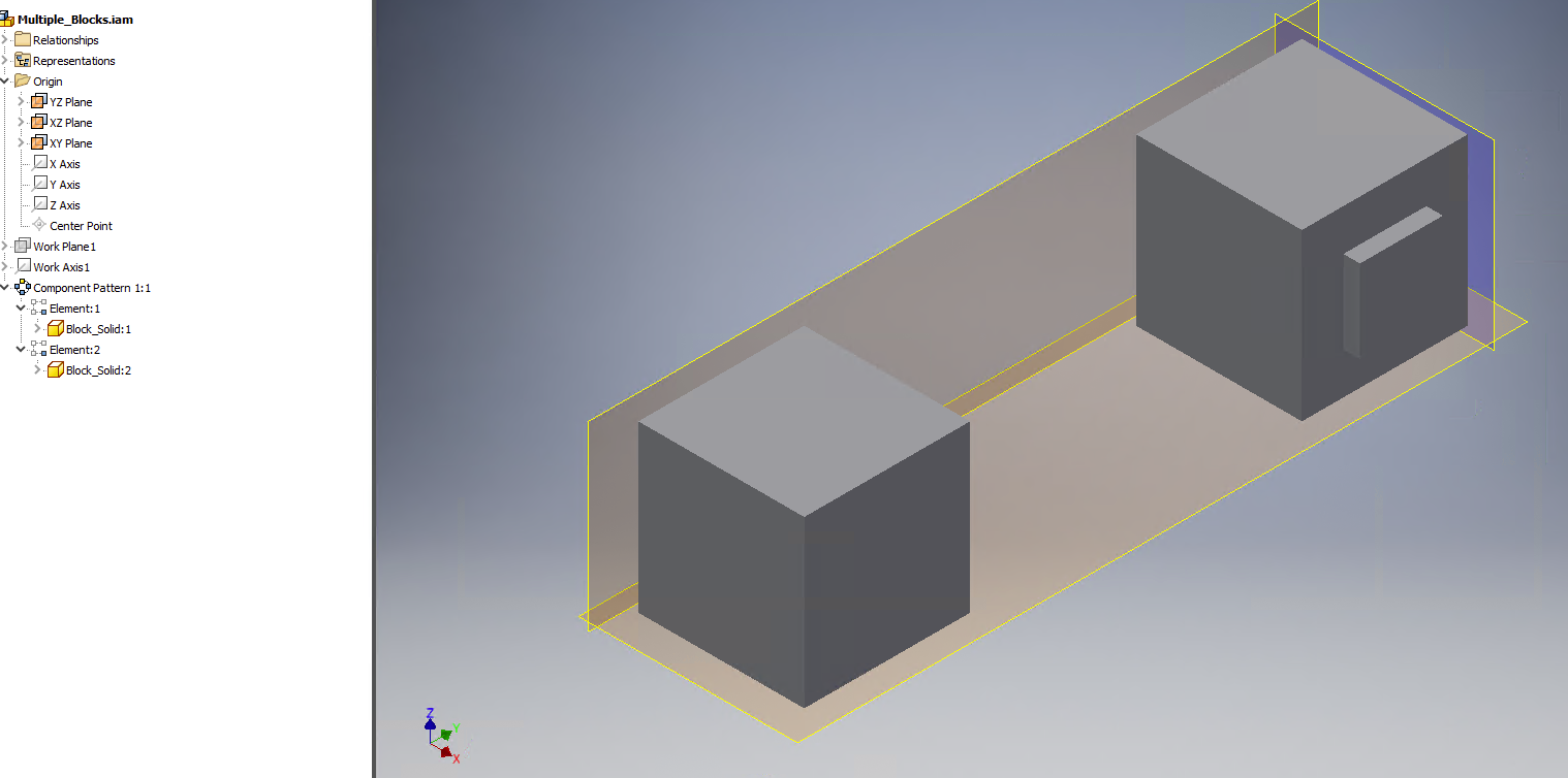
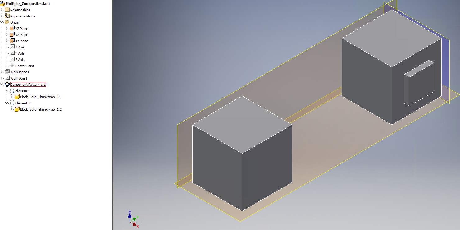
I have two assemblies created in Inventor 2019, one with two identical composite shapes (created by shrinkwrapping an assembly with just a single part, a block with an extruded feature on one side) arranged in a circular pattern, 180degrees, i.e. directly opposite one another. The other assembly has a single composite shape created by "shrinkwrapping" an assembly of two identical solid parts (same part as before) arranged exactly the same.
I imported the two assemblies into separate 3ds Max scenes, both look okay, and exported FBX (as meshes) from each scene. I imported the FBX into FlexSim as a 3D shape to replace the stock Processor's 3D shape.
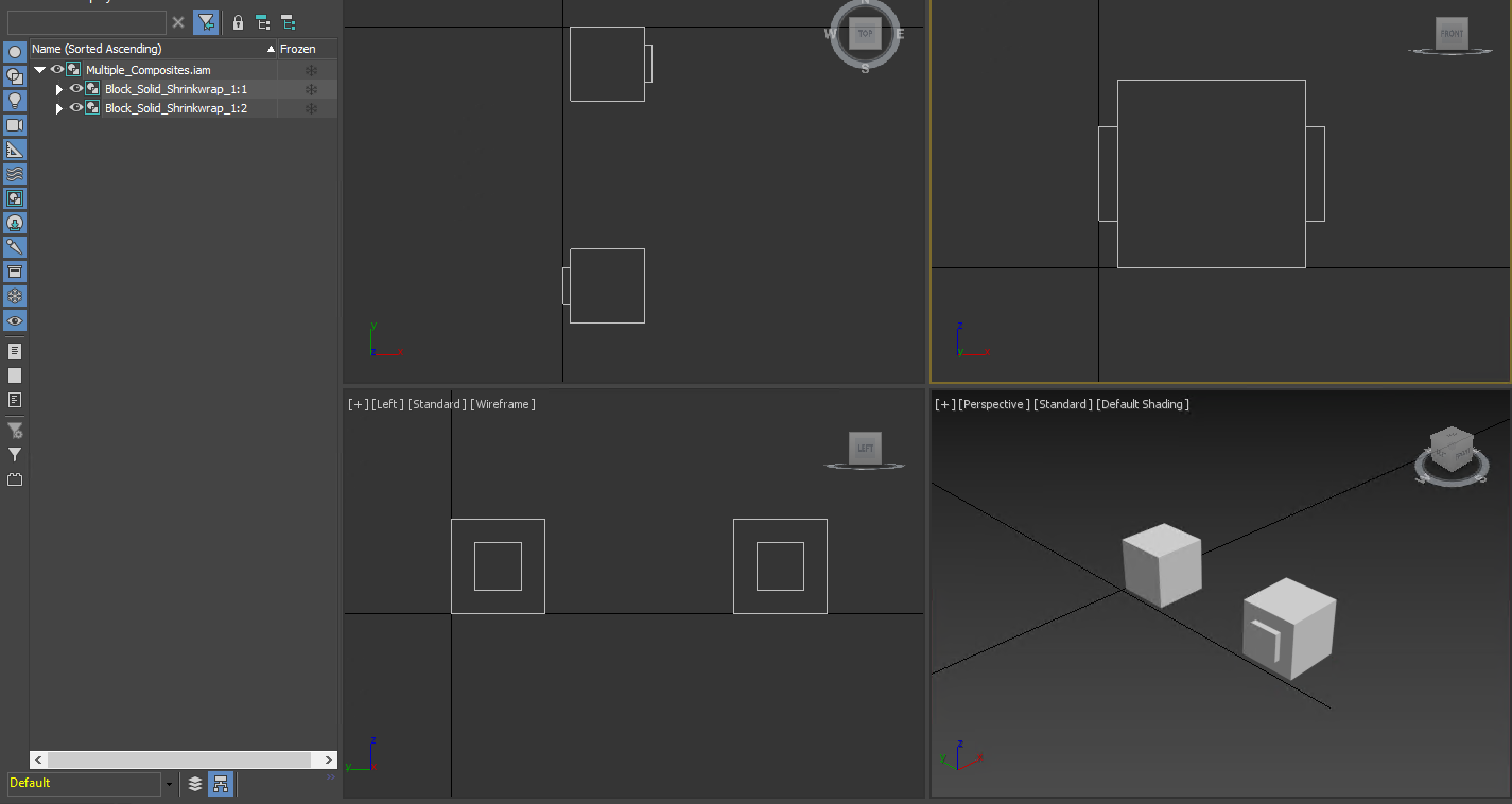
The 3D shape of the FBX created from a single composite shape with multiple objects is identical to what is shown in Inventor 2019 and 3ds Max. However, the 3D shape of the FBX created from an assembly with multiple composite shapes is slightly out of position, different from what's shown in 3ds Max. Not the entire 3D shape of two blocks, but only one of the shapes WITHIN the 3D shape, which means that I cannot re-position the one that's out of position. Please note that I imported the same FBX back into 3ds Max and it looks fine.
Any idea?
References:
Assembly of multiple solids from which I used Inventor 2019 shrinkwrap tool to create a composite part
Assembly of composite part made from an assembly with only one solid part
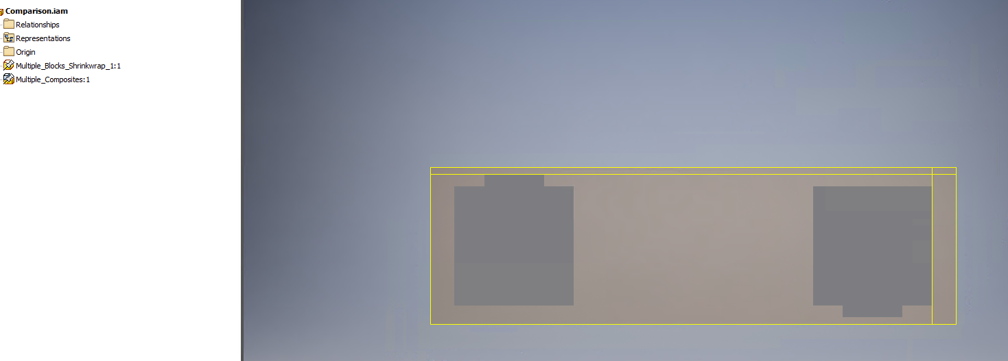
Comparison of the two cases
A single composite part imported into 3ds Max 2019
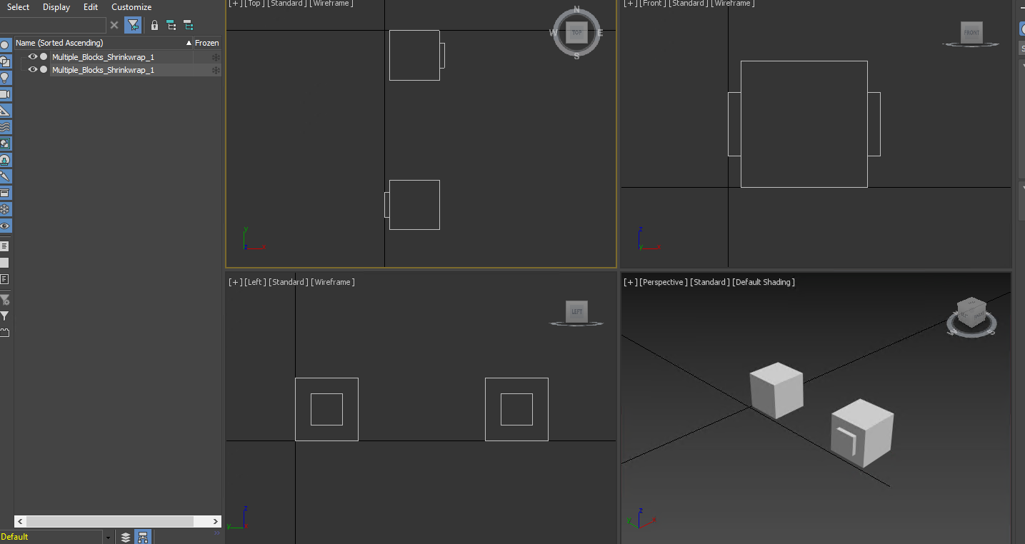
An assembly of composite parts imported into 3ds Max 2019
Imported FBX into FlexSim, this is fromthe single composite part made from multiple solid parts

This is from the assembly of multiple composites.

