question

Tommy H avatar image
0 Likes"
Tommy H asked tannerp converted comment to answer

Object within an FBX import shifted compared to as shown in 3ds Max

I don't know if this is an Autodesk Inventor issue, 3ds Max issue or FlexSim issue.

I have two assemblies created in Inventor 2019, one with two identical composite shapes (created by shrinkwrapping an assembly with just a single part, a block with an extruded feature on one side) arranged in a circular pattern, 180degrees, i.e. directly opposite one another. The other assembly has a single composite shape created by "shrinkwrapping" an assembly of two identical solid parts (same part as before) arranged exactly the same.

I imported the two assemblies into separate 3ds Max scenes, both look okay, and exported FBX (as meshes) from each scene. I imported the FBX into FlexSim as a 3D shape to replace the stock Processor's 3D shape.

The 3D shape of the FBX created from a single composite shape with multiple objects is identical to what is shown in Inventor 2019 and 3ds Max. However, the 3D shape of the FBX created from an assembly with multiple composite shapes is slightly out of position, different from what's shown in 3ds Max. Not the entire 3D shape of two blocks, but only one of the shapes WITHIN the 3D shape, which means that I cannot re-position the one that's out of position. Please note that I imported the same FBX back into 3ds Max and it looks fine.

Any idea?

References:

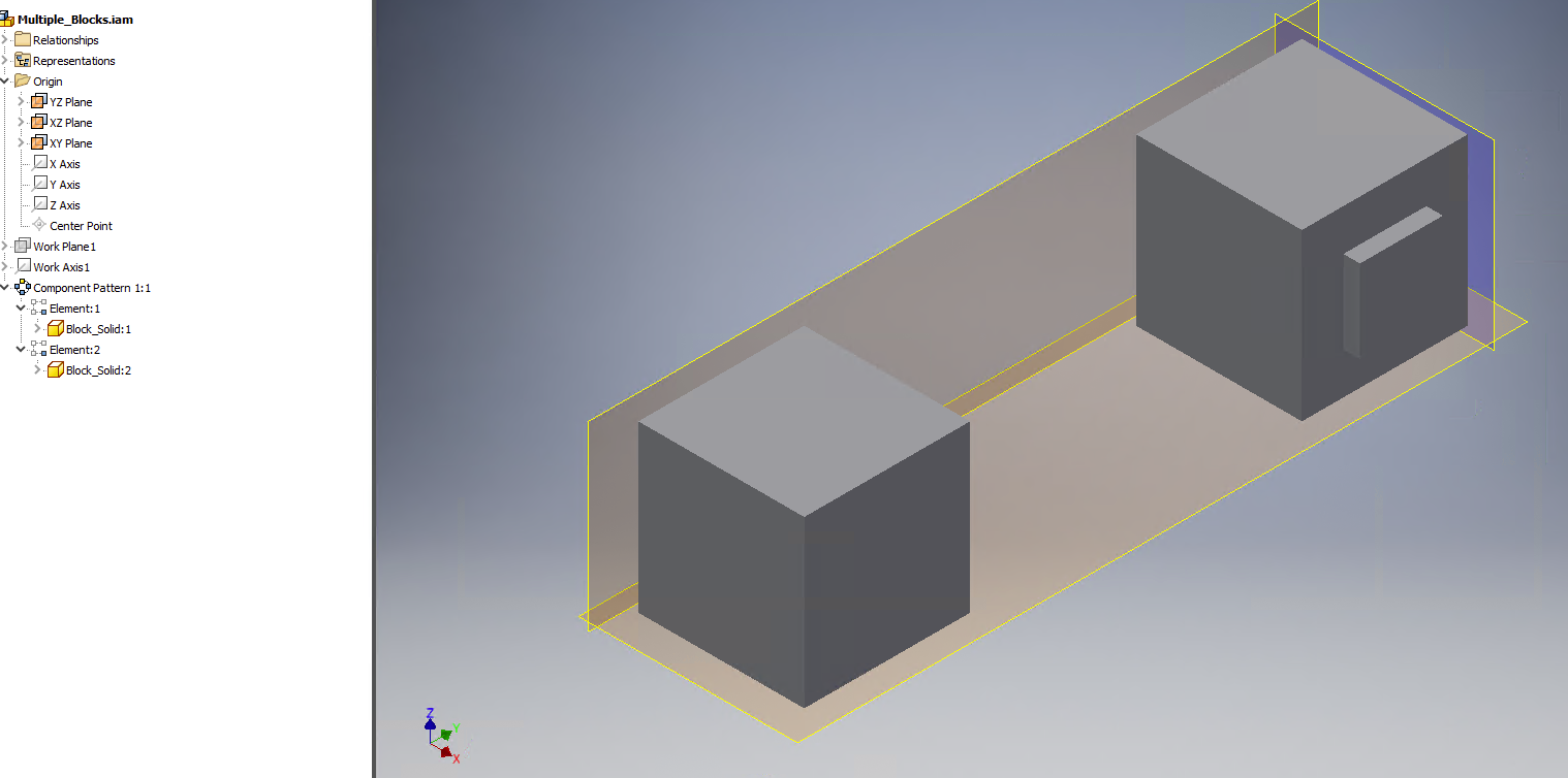
Assembly of multiple solids from which I used Inventor 2019 shrinkwrap tool to create a composite part

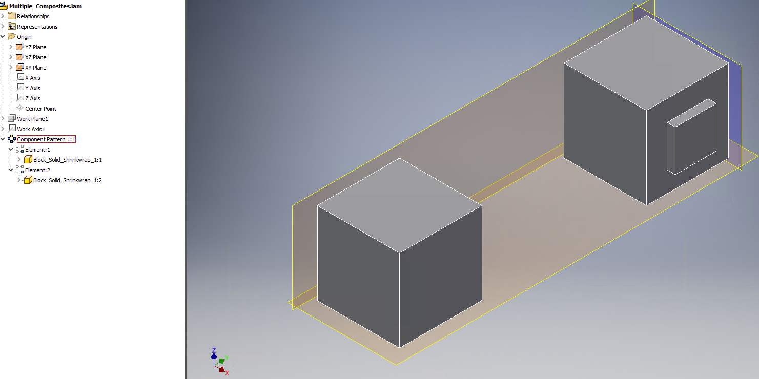
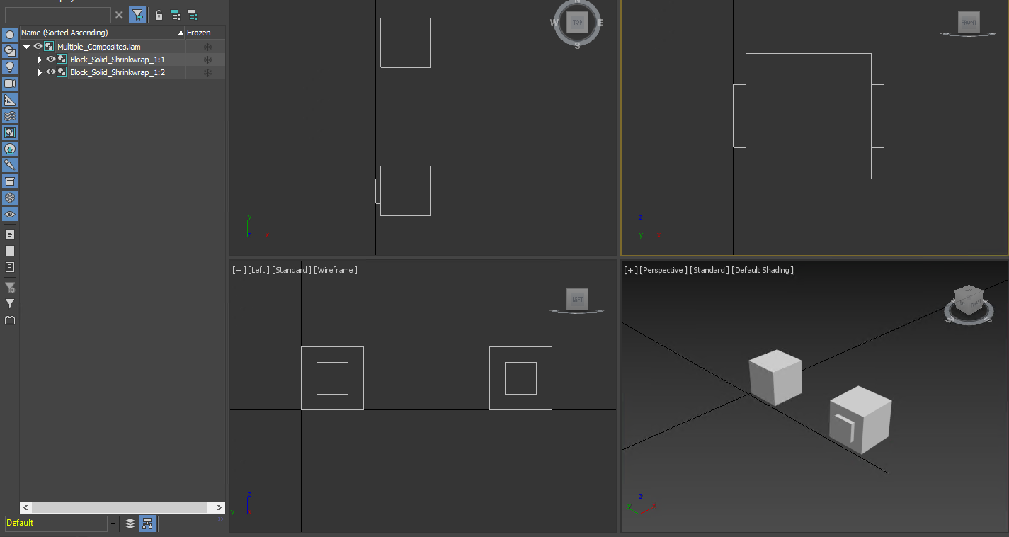
Assembly of composite part made from an assembly with only one solid part

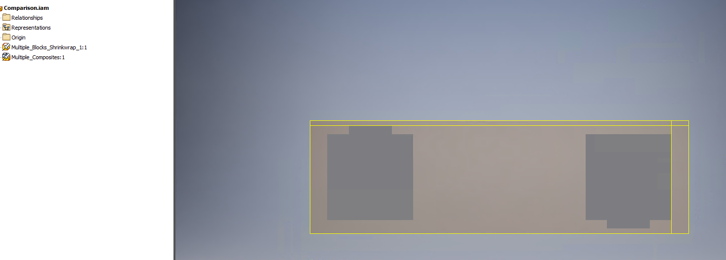
Comparison of the two cases

A single composite part imported into 3ds Max 2019

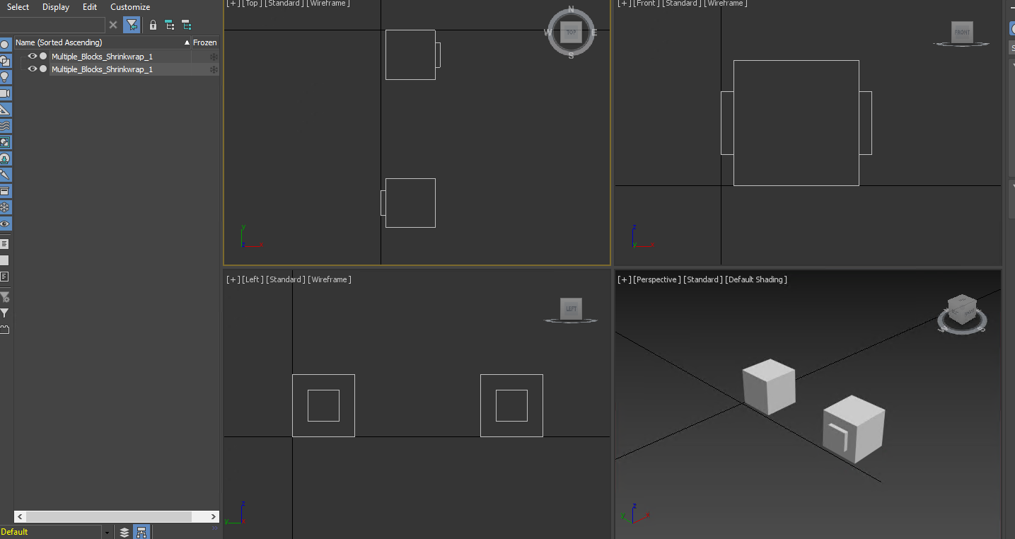
An assembly of composite parts imported into 3ds Max 2019

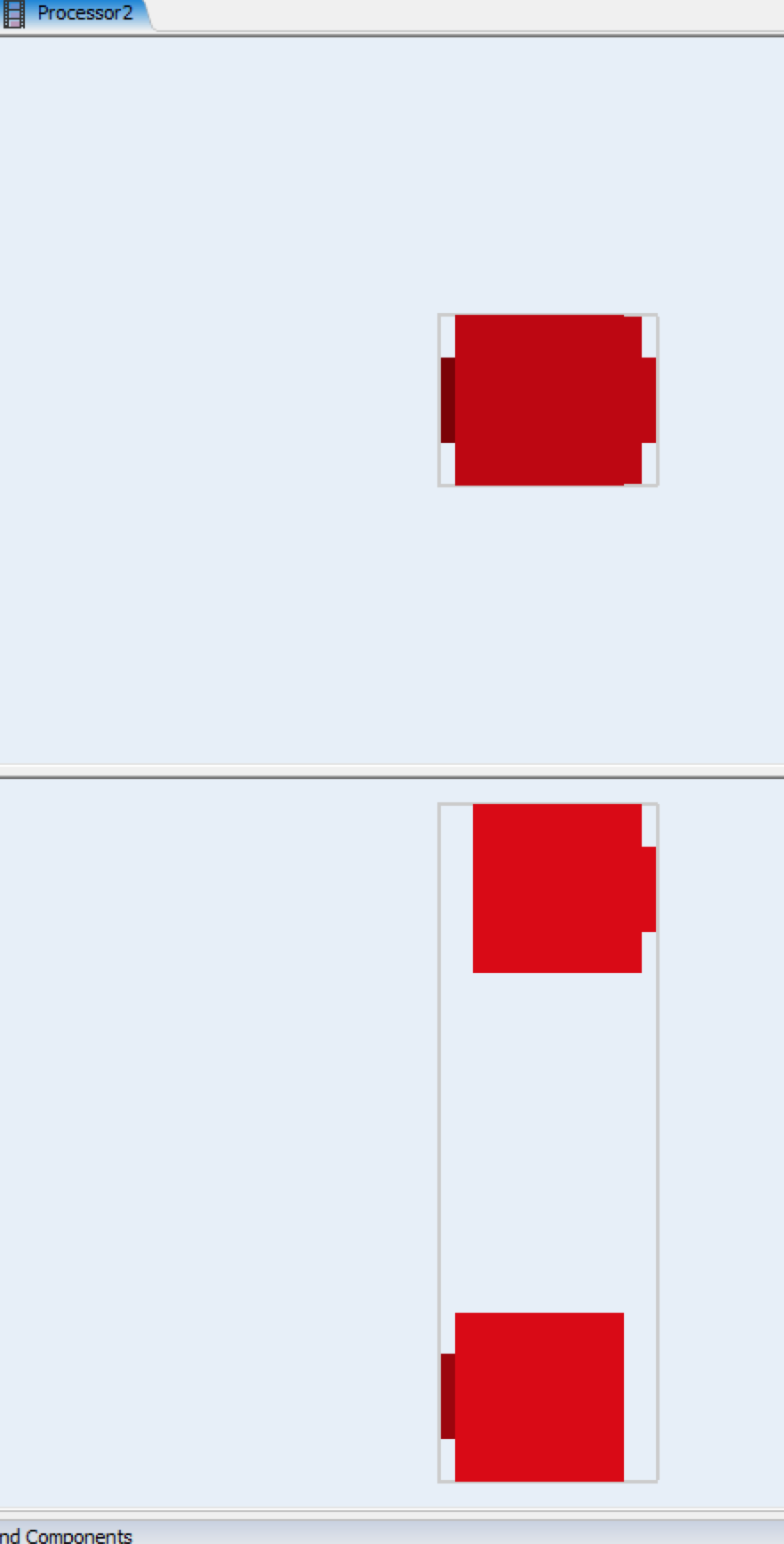
Imported FBX into FlexSim, this is fromthe single composite part made from multiple solid parts

This is from the assembly of multiple composites.

FlexSim 18.2.2
3d shapefbx3ds maxinventor
· 1
5 |100000

Up to 12 attachments (including images) can be used with a maximum of 23.8 MiB each and 47.7 MiB total.

Joerg Vogel avatar image Joerg Vogel commented ·

Thank you, to let us know that there is difference between an assembly export and a part export.

Is there an export function to store the FBX file under a different version? I know from other cad software packages that the newest program data structure isn't always the version you can import in another program without any problem. It takes some time to refine a stable export / import version. This is the case for example in step, Vrml, dxf or dwg. Please compare the results of an import of data with programs that are different to the original program used to create the data. Then if the error exists only in FlexSim, the problem is probably inside the import filter of FlexSim.

You have found a solution that works. Does the solution contain any other obstacles that you can't use it to build your shape data? Otherwise use this.

0 Likes 0 ·

1 Answer

·
Tommy H avatar image
1 Like"
Tommy H answered

In 3ds Max 2019, I am able to export using different version of FBX, up to FBX 2018. The initial test was done using FBX 2014/2015 format. I tried using FBX 2013 format, same result.

I'm not sure if it's the different between assembly export/import vs part export/import. I tried putting shrinkwrapped parts created from an assembly of multiple solids (A) into the same assembly as the shrinkwrapped parts created from an assembly of a single solid (B). I then imported that assembly into 3ds Max and selectively exported just the A objects as FBX 2013. The result was good, though not ideal.

Importing an Inventor assembly, rather than a single part, maintains the object names in 3ds Max. I can then use a MaxScript, which references the objects' name, to automatically export different combinations of objects within the assembly in multiple FBX files, very useful when dealing with multiple possible configurations of the same set of components.

The workflow that resulted in the block being shifted was my attempt at streamlining the Inventor and 3ds Max processes. In Inventor, I was hoping to only have to shrinkwrap a single instance of the sub-components, position multiple instances using constraints in whatever layout arrangements I need in a single assembly that can then be imported into 3ds Max and exported using a script to create all the different FBX that can be imported into FlexSim. In 3ds Max, instead of importing a single file with multiple identical bodies, I wanted to see if I can simplify by importing an assembly where identical parts are referenced, hoping to reduce import time.

In one case, I need 20 different configurations/combinations of the components. I either need to create 20 different shrinkwrapped parts or like 4 unique ones for the sub-components and use them in an assembly. Arranging parts in an assembly is the same either way.

My ideal workflow is as follows:

1. Start with an Inventor assembly containing multiple parts and assembly, copied from the live version.

2. Remove unnecessary parts (e.g. fasteners) and separate into sub-assemblies of moving vs non-moving parts. For a "simple" machine, I'm was able to simplify to 1 moving and 1 non-moving sub-assemblies.

3. Shrinkwrapped those sub-assemblies into a single solid part and combine separate bodies within the part into one body.

4. Put the single-body solid part into an assembly, shrinkwrap again as a surface composite body.

5. Arrange the composite parts into all the required layout arrangements in yet another assembly.

6. Import that assembly into 3ds Max, use MaxScript to selectively export combination of parts into different FBX.

7. Import into FlexSim.

5 |100000

Up to 12 attachments (including images) can be used with a maximum of 23.8 MiB each and 47.7 MiB total.

Write an Answer

Hint: Notify or tag a user in this post by typing @username.

Up to 12 attachments (including images) can be used with a maximum of 23.8 MiB each and 47.7 MiB total.