question

joc avatar image
0 Likes"
joc asked Andrew O commented

synchronize autocad dimensions with item of flexsim

Drawing1.dwg

Hello,

Hope you're well!

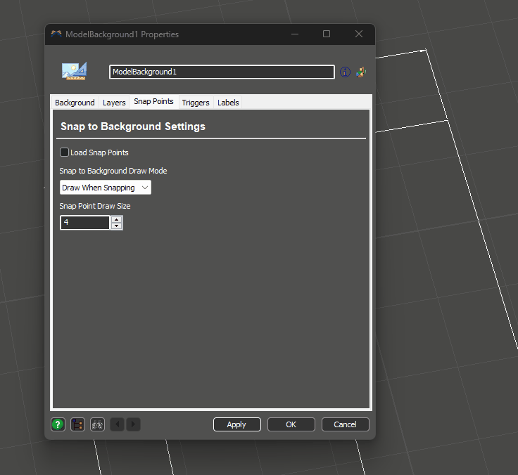
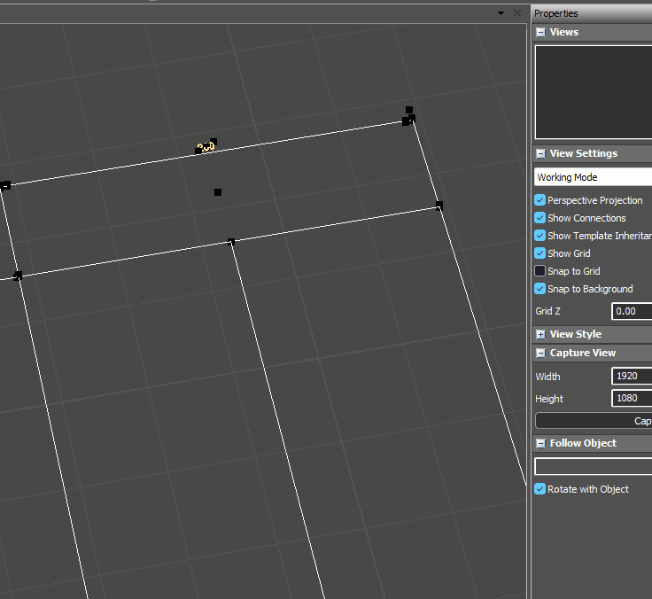
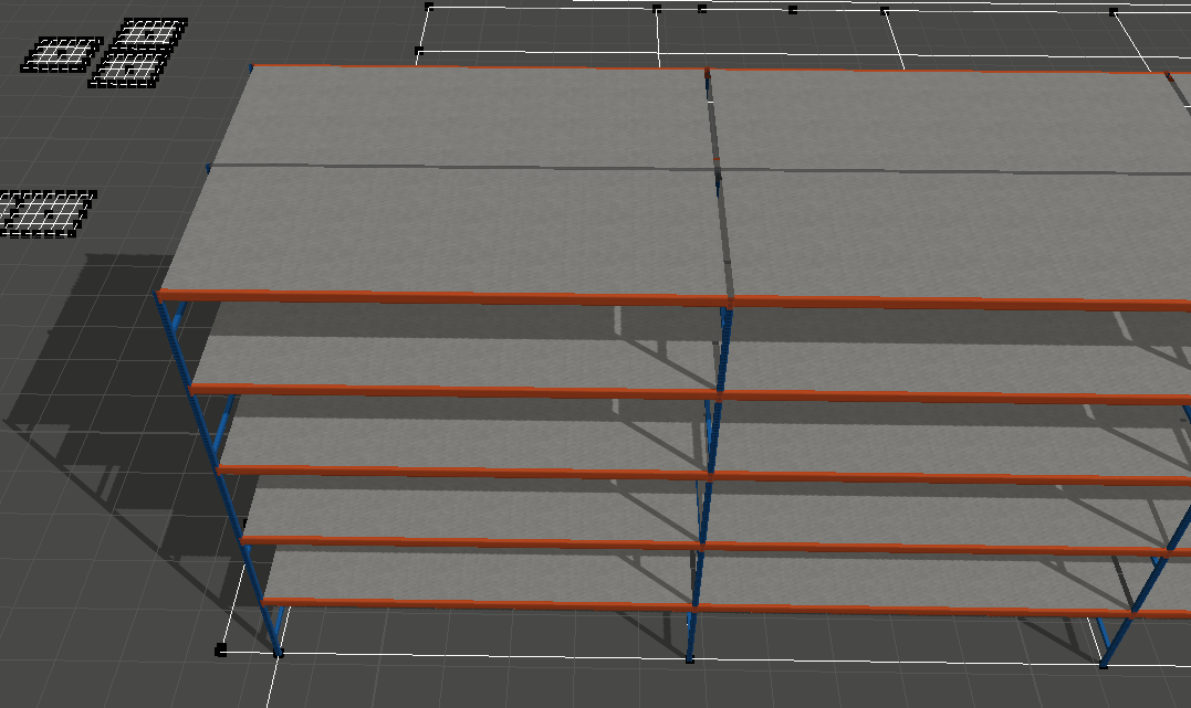
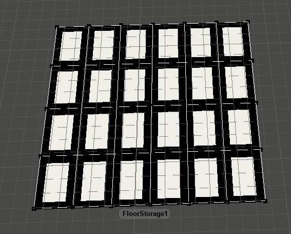
I have autoCAD file. After importing the layout, how can I put the racks (for example or any other item) exactly where they are in the corresponding design without moving them by hand.

in a few words, i want to give them an order to go exactly to the right place so that there are no deviations in simulation running test

FlexSim 22.0.0
autocaddimensions
drawing1.dwg (65.7 KiB)
· 1
5 |100000

Up to 12 attachments (including images) can be used with a maximum of 23.8 MiB each and 47.7 MiB total.

Andrew O avatar image Andrew O commented ·

Hi @joc, was Kavika F's answer helpful? If so, please click the "Accept" button at the bottom of their answer. Or if you still have questions, add a comment and we'll continue the conversation.

If we haven't heard back from you within 3 business days we'll auto-accept an answer, but you can always unaccept and comment back to reopen your question.

0 Likes 0 ·

1 Answer

·
Kavika F avatar image
1 Like"
Kavika F answered

Hey @joc, based on the .dwg file you've uploaded, I'm not sure if what you're asking is feasible. There are examples we have of people generating models based on their AutoCAD drawings using the "snap points" on your drawing (more info on snap points in the docs). However, there is not much of a way to distinguish lines from each other to specify whether something is going to be a wall or a rack (other than their coordinates). You could try parsing the line coordinates and, based on their start and end points, determine if it will be a wall or rack, but that would be tedious and take more time than if you had just simply placed the racks yourself in my opinion. You could also try separating your racks and walls into separate .dwg files and uploading them as different backgrounds, but I think that would introduce inaccuracies and would overall be ineffective.

However; there are a few methods I can recommend to enhance your model building experience with backgrounds. First, you should convert your background into the units your model uses; if your model uses meters but your .dwg uses inches, use the background conversion tool to convert it to the model units. If you don't see your model after converting, try zooming out - if your background wasn't built around the center of your AutoCAD file, then it may be off in the distance. [Note: Always try to build your model around the center coordinates of your AutoCAD environment].

Next, like I mentioned previously, you can use "snap points" to have 3D objects "snap" to your background. Simply go into your Background Properties > Snap Points tab and check the "Load Snap Points" checkbox. If you want to see them always, change the "Snap to Background Draw Mode" and increase the "Snap Point Draw Size" (something like 8 is good).

activate-snap-points.gif

Then you can snap 3D objects to these points.

snapping-queue-to-background.gif

If you want to know how big your Rack should be, you can use the measuring tool (found in View > Measure / Convert). It will appear in the bottom left corner of FlexSim. Here's an example of how to use it.

example-measuring-tool.gif

You can take that measurement and apply it to the bays in your Rack. That way, when you go to line up your racks with your background, their bays are the same width as the model. The same applies to any Floor Storage you have.

1673473629914.png

1673473654741.png

Here's the sample model I used with your .dwg file.

Snap Points Example.fsm


5 |100000

Up to 12 attachments (including images) can be used with a maximum of 23.8 MiB each and 47.7 MiB total.

Write an Answer

Hint: Notify or tag a user in this post by typing @username.

Up to 12 attachments (including images) can be used with a maximum of 23.8 MiB each and 47.7 MiB total.