question

Julio R avatar image
0 Likes"
Julio R asked Ben Wilson edited

Map location data import

Hello,

I have a project where I have to position a lot of addresses into a big map. I have the addresses and I have

automatically mined the latitude-longitude data from google server. My question is: how can I create objects based on that information that maches my map?.

I can´t do this manually because there are too many and it will take too long, so I need a way to convert de latitude-longitude coordinates to a x, y coordinates in the model.

Last week I was investigating and latitude-longitude can´t be transformed into cartesian coordinates like the ones FlexSim uses easily, so I´m thinking a few ways to do this, but I haven't been abe to do any:

Change the work coordinates of FlexSim. I know this may be impossible, but if I could that would solve the issue really fast.

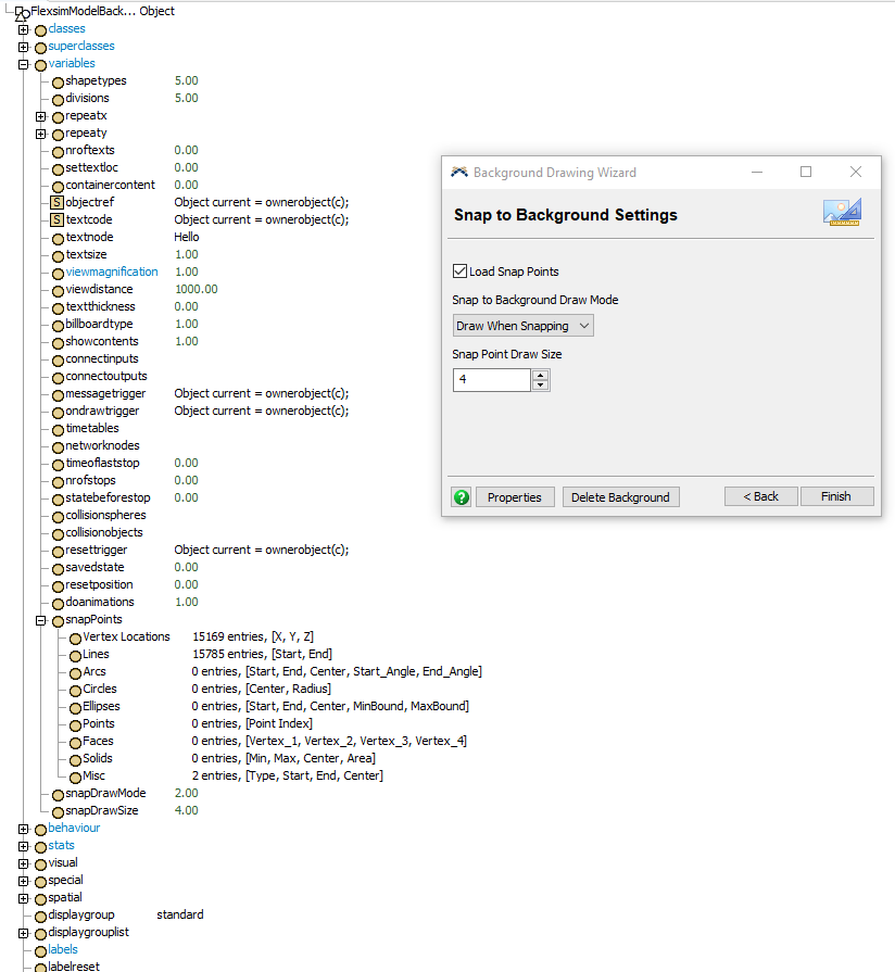
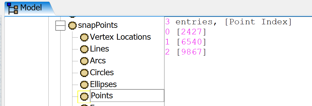
Load data points from a DWG. I already have the points drawn in a DWG document, but I cannot identify which point is which and there are too many(more than 3000). If I can unload the points information I could track an id of each point, but again I don´t know if that is possible.

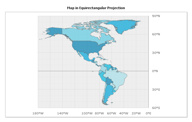
Translate world coordinates to pixel coordinates. I already can translate the coordinates to any world coordinates (longitude-latitude, UTM, etc) but I cannot translate that to cartesian coordinates without a significant distortion.

FlexSim 18.0.1
coordinatesdwgmapdata import
5 |100000

Up to 12 attachments (including images) can be used with a maximum of 23.8 MiB each and 47.7 MiB total.

Ben Wilson avatar image
0 Likes"
Ben Wilson answered Ben Wilson edited

@Julio R,

For a direct translation of longitude/latitude to x/y, using an Equirectangular map should do the trick, "because of the particularly simple relationship between the position of an image pixel on the map and its corresponding geographic location on Earth."

This projection just forces the longitude lines to be parallel, and keeps both latitude and longitude lines equidistant.

So, there is distortion (as there is in any map projection), but the continent outlines and political boundaries are drawn according to the projection, so someone watching the simulation would easily know what is going on, and all your simulation objects would be in their proper place, since the proper longitude/latitude coordinates will map perfectly to the proper x/y location.

So I think if you just use an Equirectangular map for your image, you will be fine.


· 2
5 |100000

Up to 12 attachments (including images) can be used with a maximum of 23.8 MiB each and 47.7 MiB total.

Ben Wilson avatar image Ben Wilson ♦♦ commented ·

Oh, sorry, looks like you're working with a CAD drawing or something else that is already in a particular projection.

Perhaps this article could help you determine which projection your data image is in.

Or perhaps you can switch to a different image, and just use the lat/long info?

0 Likes 0 ·
Julio R avatar image Julio R Ben Wilson ♦♦ commented ·

Thank you @Ben Wilson,

I checked that solution and it works perfect, I have no problem changing the map. I just need a good map with roads of north America in that coordinate system, but I'm sure there are many.

I can't believe I missed that coordinate system, I was looking for far more complicated solution.

0 Likes 0 ·
Phil BoBo avatar image
1 Like"
Phil BoBo answered Ben Wilson converted comment to answer

"but I cannot translate that to cartesian coordinates without a significant distortion"

That's natural when you try to flatten sphere coordinates onto a flat plane. See map projections.

"Change the work coordinates of FlexSim."

I don't know what that means. You can manually change the nodes in MODEL:/Tools/ModelUnits. Technically FlexSim units can be whatever you want them to be. The model units are so that a modeler can specify what the units are and then be consistent everywhere. Also, they are used for scaling the library objects so that they have reasonable default values.

"Load data points from a DWG."

You can check the Load Snap Point box in the Background Drawing Wizard window in order to load the point data from the DWG into the tree so that you can access the data. The data gets stored in subnodes under MODEL:/FlexsimModelBackground>variables/snapPoints:

"how can I create objects based on that information that maches my map?"

You can create objects with the createinstance() command and position them with Object.setLocation(). You can programmatically do this within a loop that traverses the data imported from the DWG. Knowing what values to specify for X and Y in setLocation() is the question.

I built a model where the data for locations was in lat/long and I wrote a user command that took lat/long pairs and returned the associated x/y coordinate in my model. The user command I wrote was such that the returned x/y coordinates matched up with the projection of the DWG map that I imported of the area. This project was a reasonably small area geographically and not the entire world, so the distortion wasn't so bad.

Creating the objects at certain points on a given projection isn't the main difficulty. The difficulty comes when you need to travel between those points. You can't simply use pythagorean distance to travel in a straight line. Rather, you need to use a command that calculates the distance to go from one point to another. The projection distortion will distort your results if you use pythagorean distances rather than a custom calculation. Depending on what you are modeling (airplanes, ships, trucks, etc.), the distance traveled from one point to another might be different (roads, shipping routes, etc.). That's the actual tricky part in this type of model. Depending on your modeling situation, you might be able to get distances from a web api, such as the google maps example in this answer.

Finding pseudo-code to translate from lat/long to a projection coordinate system shouldn't be too bad. For example, Convert Lat/Longs to X/Y Co-ordinates. Depending on the projection used by your DWG, you may need to adjust the conversions you find so that it works well for your particular project.


snap-points.png (77.6 KiB)
· 1
5 |100000

Up to 12 attachments (including images) can be used with a maximum of 23.8 MiB each and 47.7 MiB total.

Julio R avatar image Julio R commented ·

Hi @phil.bobo ,

I open the link you sent me, there is a very promising code, but I couldn't make it work. Could you help me? Also it doesn't say what system of projection is using, and I think without it you could not do that, I hope I'm wrong and it works for any projection system.

map-script.fsm

I had tried what you said about converting directly latitude and longitude to x, and y, but I'm working with North America map, so the distortion is significant.

I am planning on doing the web api search for the distances, so it's only important for a graphic aspect, my problem is that if the distortion is too much, my objects will end up in the middle of the sea or on another state.

I've looked the snap points on the tree, there is a identification number and a Point Index number, what do they mean? How can I know the coordinates of those points?

0 Likes 0 ·
map-script.fsm (12.9 KiB)
capture.png (22.0 KiB)

Write an Answer

Hint: Notify or tag a user in this post by typing @username.

Up to 12 attachments (including images) can be used with a maximum of 23.8 MiB each and 47.7 MiB total.