question

Tommy H avatar image
0 Likes"
Tommy H asked Phil BoBo edited

Import 3D CAD models from Inventor

I'm currently evaluating FlexSim 2018 Update 2 to see whether it's suitable for my work. We design special-purpose machines and industrial automation (production lines, etc) for general manufacturing industry.

I understand that FlexSim supports 3DS, STL, STP, etc. What's the recommended workflow for importing an assembly created in Autodesk Inventor 2017+ into FlexSim and animating them?

For the proof of concept/capability, I'm using one of our existing design, a single-axis lifting jack. I've simplified the machine into big chunks, grouping parts that move together and simplified them (in Inventor) into a solid body part. I end up with a fixed base and one single moving part that just move up and down.

I've experimented with using 3DS Max and Blender, though haven't had much success. In one case, the model's scale is out by 1000, that happened when I imported an ASCII STL exported from Inventor. Could someone suggest how to go about getting these two Inventor parts into FlexSim and making a Fixed Resource out of it? I'll eventually need to have 16 of these thing make up a single Fixed Resource as they work as a set. Any suggestion on how to do that?

FlexSim 18.2.2
3d modelimporting 3d filesinventorautodesk
5 |100000

Up to 12 attachments (including images) can be used with a maximum of 23.8 MiB each and 47.7 MiB total.

1 Answer

·
Phil BoBo avatar image
2 Likes"
Phil BoBo answered Phil BoBo edited

File Formats

3ds Max can import Inventor's native file format. Then you can export from 3ds Max to FBX, which imports very nicely in FlexSim. Using this process, you will lose the least amount of information about your shape in file format conversions.

The other formats that Inventor can currently export that FlexSim can currently import (IGES, STP, and STL) do not contain material information. So you will lose the color information on each part of your shape. Instead, it will use the main object's color for each part of the shape in FlexSim.

Inventor has a third-party paid add-in that enables it to export obj, which is a format that contains material information. FlexSim can import obj files. That could be an option for you. I think you can get a free trial of that add-in if you wanted to test it to see if it works for you.

Inventor can also export DWG files, which FlexSim can import. In FlexSim, the Model Background object imports DWG files by default. In other places where you select 3D shapes, DWG files aren't shown in the File Browse Dialog window by default, but you can type *.dwg into the file name to show them and select them. The DWG importer is a custom third-party renderer that FlexSim uses rather than importing the file directly. This is great for compatibility with various AutoCAD features, but it may be better for you to get your Inventor shape into FlexSim using a regular 3D shape format, such as FBX or OBJ rather than the AutoCAD native DWG format.

Applying Multiple Shapes to One Object

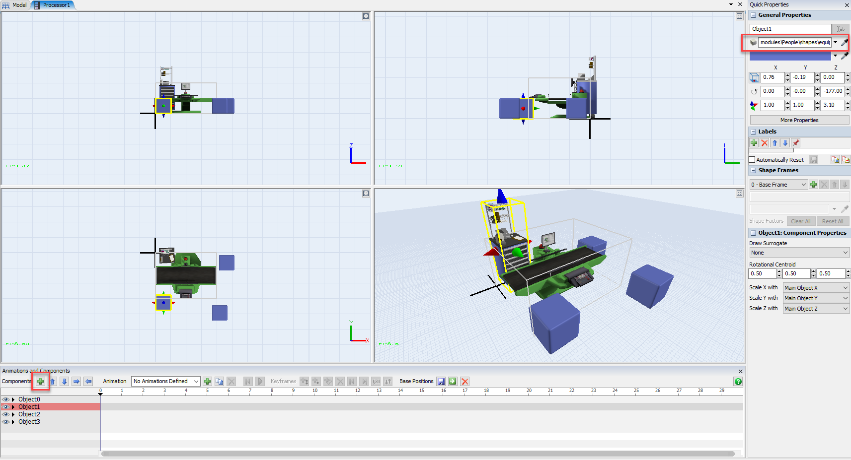
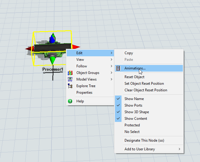
If you right-click on an object in FlexSim, you can select Edit > Edit Animations to open FlexSim's Animations and Components window:

In the Animations and Components window, you can add sub-components to your object, which can each have their own 3D shape and positions relative to each other.

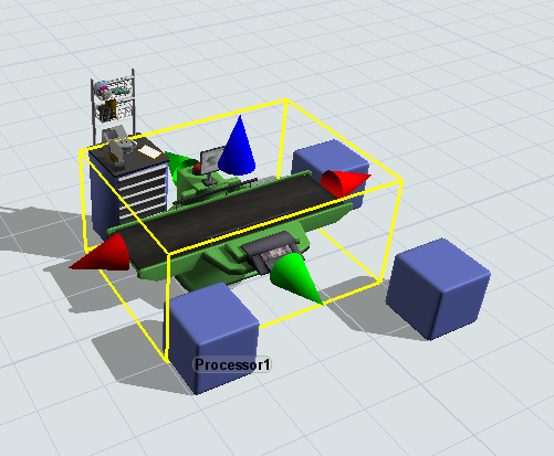
You can animate those sub-components individually and they will render as a single object in the 3D view:


· 7
5 |100000

Up to 12 attachments (including images) can be used with a maximum of 23.8 MiB each and 47.7 MiB total.

Tommy H avatar image Tommy H commented ·

Thanks, @phil.bobo. I managed to get through the first step of bringing in the model from Inventor. I'll try the animation next.

Result:

Following @phil.bobo's advice, I started with a native Inventor 2019 .ipt file, which is a shrinkwrap version of an assembly of static parts. The Inventor assembly file (.iam) has document length unit in "mm", modelled with z-axis up, components are all grounded. I created the shrinkwrap part file with multiple solid bodies.

I imported the .ipt file into 3ds Max 2019, specifying "Meshes" and "Z Axis" as Inventor File Vertical Direction. 3ds Max "System Unit Setup" 1 Unit = 1.0 Meters. I then exported an .FBX format, automatic scale factor, "Y-up".

Importing into FlexSim, I started with a model with length units in "millimeters" (though "meters" was okay as well). I used a "BasicFR" fixed resource and changed its 3D shape to the FBX file.

Comments

The key here seems to be the System Unit Setup in 3ds Max set to "1 Unit = 1.0 Meters" and the exported FBX "Up Axis" set to "Y-up". Earlier attempts resulted in FlexSim shapes being 1000 times too big when I had "1 Unit = 1.0 Millimeters" even though Inventor had millimeters as length unit. I had also specified "Z-up" in the FBX Export dialog and ended up with my model on its side.

The Inventor document length unit in mm is also important. At some point, when I imported into FlexSim, the scale was out by and additional 25.4. I imagined somewhere up the line, most likely in Inventor, the unit was set incorrectly. I'm using a new installation of Inventor on a clean PC, working with a Pack-and-Go assembly without the template files.

1 Like 1 ·
Tommy H avatar image Tommy H Tommy H commented ·

Further to above, the animation part was very straight-forward. I tested with a single instance of the static part, imported it into FlexSim as above. Then in the Animation Creator, I added a subcomponent and changed its shape to the moving part. I added a keyframe at time 0 and time 10, changed the position of the moving part at time 10, done.

For multiple instances of the static/moving parts. Instead of placing multiple subcomponents, I went back to Inventor, created an assembly, added and positioned multiple instances of the part, then shrinkwrapped the assembly into a single part. I imported that into 3ds Max, exported FBX, then imported that into FlexSim. Repeated the process for the moving part. The end result is pretty good. I think I've proven that FlexSim can import and animate detailed representation of our machines, albeit with a bit of processing.

1 Like 1 ·
Kenny Macleod avatar image Kenny Macleod Tommy H commented ·

Yup 25.4mm to an inch.

0 Likes 0 ·
Clair A avatar image Clair A commented ·

As Phil has mentionned, it's possible to export from Autodesk Inventor to an OBJ file. In a project our client provided us an Autodesk Inventor file originally in the JT format. The 3D object was in millimeters, so first I changed the scale to meters in Inventor. Then I saved the file as OBJ, which actually creates 2 files: one OBJ file for the 3D + one MTL file for the materials. When importing the obj file in FlexSim, the rendering was very good, with the same colors as in Autodesk.

1 Like 1 ·
Tommy H avatar image Tommy H Clair A commented ·

I tried to export in OBJ format, but Inventor 2019 took way too long to export, 10+ minutes for a shrinkwrapped part file. The file size was also huge compared to FBX export, 500MB for OBJ file vs 10MB for FBX.

Also, a problem I had with formats other than FBX was that there was no way to change orientation from Z-up to Y-up (which can be specified in the FBX export dialog). STP, STL and 3ds files were all in the incorrect orientation when they were imported into FlexSim. I re-oriented the shape in the object properties, but in the Animation tool, the static shape was still in the original (incorrect) orientation and I couldn't figure out how to fix this (edit shape factor maybe?).

1 Like 1 ·
Phil BoBo avatar image Phil BoBo ♦♦ Tommy H commented ·

Yes, if the shape loads in an incorrect orientation, you should edit the shape factors to appropriately position the shape in its yellow box. Shape factors are designed to compensate for offsets needing to be applied to the shape.

And I agree that FBX is certainly a preferable format over OBJ.

1 Like 1 ·
Tommy H avatar image Tommy H commented ·

Hi Phil,

Thanks for that. A follow-up question, I saw another one of your posts about rigging meshes to bones before exporting an FBX file and importing it into FlexSim to maintain the animation (https://answers.flexsim.com/questions/33881/flexsim-animation-problem-with-3ds-max-fbx-export.html). I'm wondering, is that an easier way to deal with animating assemblies imported from Inventor?

I work with other designers/engineers who design machines/parts in Inventor. I will have to deal with assemblies that could change over time. If I rig the machines' meshes to "bones", then perhaps I could replace those meshes when there's an updated release of the machine. How would FlexSim deal with that?

Just to put things in context, we want to use a discrete event simulation tool, e.g. FlexSim, to better visualise our machine designs in a production line. Obviously, we'll have to simplify the machines' models, but being able to show detailed 3D models in a proper dynamic simulation is one of the reasons we're looking at FlexSim.

0 Likes 0 ·

Write an Answer

Hint: Notify or tag a user in this post by typing @username.

Up to 12 attachments (including images) can be used with a maximum of 23.8 MiB each and 47.7 MiB total.