question

Craig DIckson avatar image
4 Likes"
Craig DIckson asked David Seo edited

Modeling AMRs using AGV paths or using A* - can you find me a better way?

Starting with Kiva Systems (now Amazon Robotics) several years ago, and increasing rapidly in the last 2-3 years, AMRs ("autonomous mobile robots") have become very common in the materials handling industry. That trend will continue: AMRs are now replacing conveyors in even large distribution systems. (My employer, a well known distribution system integrator, has not sold a primarily conveyor-based system in 3 years, and I know we are not alone in that.) I am hoping that FlexSim can keep up with this trend so that modeling AMRs becomes as straightforward as modeling conveyors is.

A defining characteristic of AMRs is that they turn by rotating, at 90 degree intersections. It would be hugely helpful to many customers - not just me - if you could add this functionality to the AGV construct in FlexSim. (If I recall correctly, AGVs can actually make right angle turns already, except that they snap to the new direction in zero time. This suggests to me that this may not be that difficult of an addition.)

I know of two ways to model AMR travel in FlexSim now, and have used them both successfully. But neither is really satisfactory:

1: On one large model, I used A*, since it does allow for this type of turn. I found several limitations to using A* for AMRs. First off, all stop/queue/pickup/dropoff locations must be on the grid, with nice even spacing. This is often not the case in real life, particularly on large full-warehouse systems which are increasingly common in the distribution industry. (Think of a set of workstations that are spaced on 1 meter increments ... except the one that is 1.35 meters apart because of a building column.) If you make the grid smaller to accommodate this (i.e., grid spacing = least common denominator), then AMR accumulation usually does not work correctly. Stopped vehicles occupy only one grid location at a time, so if the grid is smaller than the vehicle they run in to each other when queueing. Moreover, you cannot force a vehicle to an exact location in A* -- it will stop at a nearby grid position if A* thinks it is "close enough". You can configure it, but only down to a distance of +/- one grid space, which still may leave the vehicle in a travel path when you sent it to a spur. Once again a smaller grid can help some, but it's never perfect and as noted above makes accumulation wrong. A smaller grid also makes defining paths far more tedious (you have to block out entire rows of grid positions so the AGVs don't go around each other when they shouldn't). (I do understand why A* works this way (it was designed initially to model people, and "close enough" reduces the complexity of the calculations), but that makes it a poor fit for modeling AMRs.)

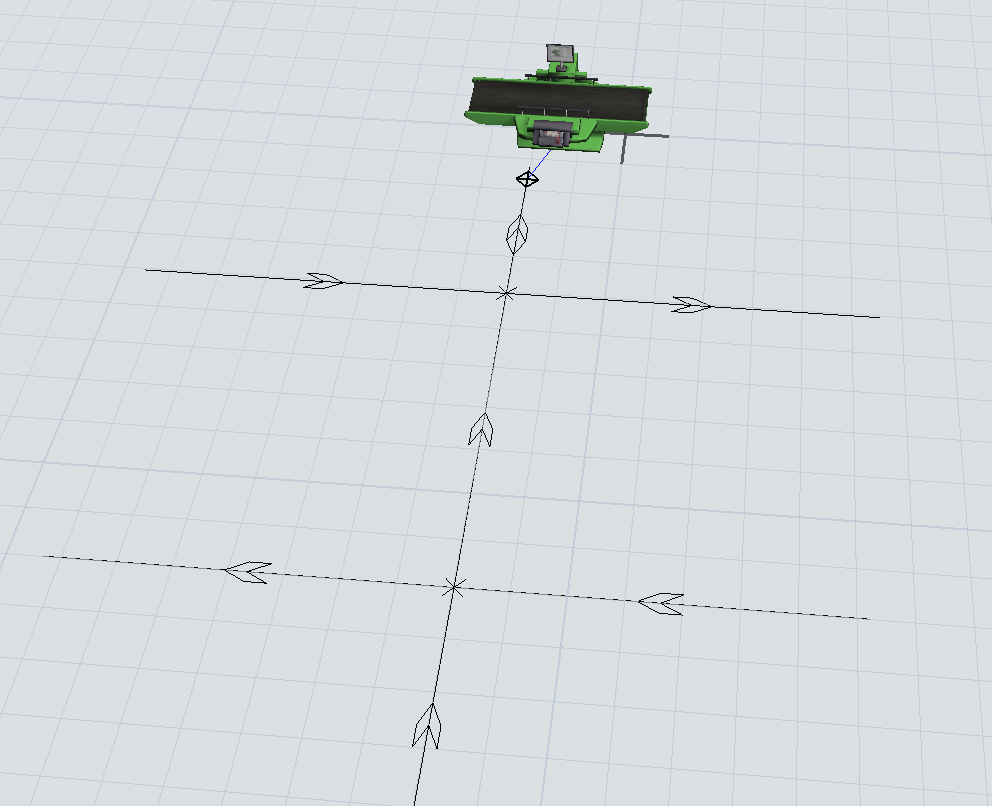
2. In some other models, I used AGV paths, control points, zones etc., and then modeled the spin-in-place turning behavior using very small radius turns (typically <= 12"), with the speed on those turns set appropriately low (~4 ips, when the straight speed is 48 ips). 1646955281664.png
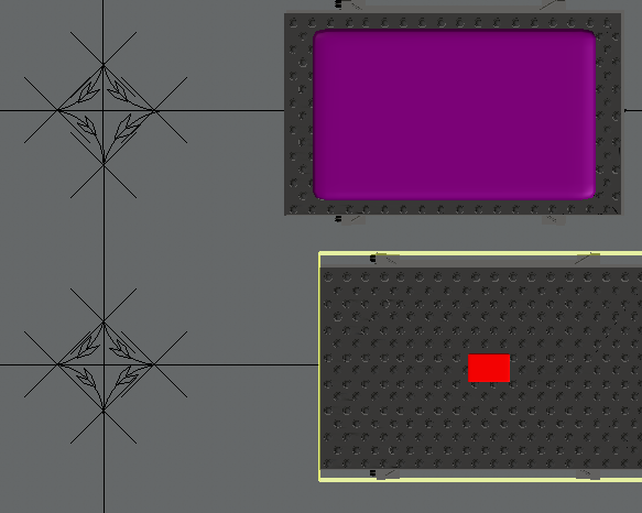
This looks ok (though not perfect) but it is tedious to get all of the little curves actually attached correctly. Worse, if you change e.g., the length of one of the straight paths, you have to re-attach virtually every one of the small paths at every intersection. Also, for some reason control points really really want to snap to the little curves not the straights, so it is all but impossible to put a control point near the intersection. It is pretty obvious that the developers did not anticipate users drawing small curves like this.

I will also point out that these models do not use the AGV process flow, since AMRs, unlike AGVs, typically do not travel looking for work -- the central WES (warehouse execution system) just tells them where to go. Thus no changes to the AGV process flow would be needed. In fact my custom process flow of this approach is very simple, so if I did not have to jump through the hoops of all those little curves, I could model an AMR-based system as rapidly as a conveyor based system.

But as it stands now, the FlexSim modeling process of AMRs is taking just as long as building something custom in Python (which my manager is having other analysts do as we speak). For obvious reasons that is not in your or my best interests!

Thanks for reading my whole screed ...

Craig


FlexSim 22.0.1
agva starspin in place
1646955281664.png (111.8 KiB)
· 2
5 |100000

Up to 12 attachments (including images) can be used with a maximum of 23.8 MiB each and 47.7 MiB total.

Joerg Vogel avatar image Joerg Vogel commented ·

@Craig DIckson , if A*Star is not suited for you, you can take up my approach some years earlier before A*Star grid was introduced. Each AGV splits its path to drive on rectangular style. A table layout setup a grid. Item racks are send from one queue to another queue or to a drop of object or pick up object. The main idea behind table layout and queue placement is, you can place items anywhere in a model, because you can switch off any stacking method in queues.

Ticked time intervals can be dynamic and be set to small intervals only for vehicles passing or colliding in grid tables. My example contains only an really simple routing system, which lets vehicles drive typically down to a horizontal path and up on vertical aisles to get to a grid cell. The system has got no collision control mechanism at all.

Any tasksequence is a result of a sequence of travel to location tasks and a delay time to impose a rotation if a direction changes.

Today I would combine a simple routing mechanism with the multiple agent system module to get a collision detection system. But a table driven approach with a short timed available list can be used for a collision detection, too. A list approach would consists of pushed table cells and dynamic field values. A logic would grant an vehicle with highest priority a passage through an area of possible collision by pulling an set of cells from such a list.
Please look for Topic keyword kiva to find my demo model.

https://answers.flexsim.com/questions/72454/kiva-project-simulation-example.html

0 Likes 0 ·
Jeanette F avatar image Jeanette F ♦♦ commented ·

Hi @Craig DIckson, was anthony.johnson's answer helpful? If so, please click the "Accept" button at the bottom of their answer. Or if you still have questions, add a comment and we'll continue the conversation.

If we haven't heard back from you within 3 business days we'll auto-accept an answer, but you can always unaccept and comment back to reopen your question.

0 Likes 0 ·
anthony.johnson avatar image
1 Like"
anthony.johnson answered Steven Hamoen edited

Hey Craig,

I definitely want to improve FlexSim's features for these types of situations. Right now I think the best way forward would be improvements to A*:

1. Solve/improve the grid spacing problem by increasing the flexibility of combining different grids, with different node sizes, together. If you could snap the edge of one grid to the edge of another grid, for grids with different node sizes, and have FlexSim automatically calculate the 'bridges' between the nodes on those two grids, then I think that would get you 90-100% of the way toward what you need. You can essentially 'tile' different grids of different sizes together to get the layout you need.

2. Implement better traffic control mechanisms in A*. Having an 'A* control area' would go a long way. Also, refactoring the A* algorithms to be more open and programmable, so that the user, if they need, could design their own traffic avoidance, path planning, etc. algorithms.

At this point my opinion is that A* is the best way forward for this. While I still want to make improvements to AGV, I don't think those improvements would necessarily be directed to these types of scenarios, as I think A* is closer to that end goal. And obviously feedback is appreciated.

· 6
5 |100000

Up to 12 attachments (including images) can be used with a maximum of 23.8 MiB each and 47.7 MiB total.

Patrick Zweekhorst avatar image Patrick Zweekhorst commented ·

Hi @anthony.johnson ,

Thank you for your explanation and your ideas on the A* network. Talumis also has some ideas and input for this discussion which I will try to explain below.

We agree with Craig that modelling AMRs is currently not as straight forward as it can be. We have done multiple projects the last few years where we had to model AMRs. We did all of those by using the AGV network. Like Craig we used very small and slow curves to model the AGV where it was rotating on the spot. We think there are a lot of benefits for the AGV network over the A* network for modeling these situations. Some very useful features in the AGV network include:

  • Accurate locations for the vehicles to travel to. They just travel over the specified path, exactly to the location where we want it to go. This also included the orientation and rotation for the vehicle. When driving into a rack the rotation should precisely match the rotation of the rack for example. The orientation of the vehicle is also important, because the vehicle sometimes needs to drive backwards before it can make a turn. Or when the vehicle needs to drive backwards into a spur.
  • Rerouting vehicles when they arrive at a certain point on the route. For this we would now use the OnPreArrival trigger of certain control points on the route. With A* this is currently not possible (as far as we know).
  • Different speeds for different sections of the layout is very easy with the AGV network. This also holds for acceleration and deceleration.
  • Driving below/under objects can just be done by laying a path at the desired location. When we would do this with A* we can’t connect the object to the A* navigator, since in that case the vehicles is not able to drive at the path. We would need to add barriers at the different locations of the object where the vehicles should not drive.
  • Traffic control rules can be made relatively easy in the AGV network. This includes control areas, but also the maximum number of allocations at control points. In combination with ProcessFlow giving preference for vehicles from the main paths over the vehicles from the smaller path can be done without any problems.
  • Accumulation control is pretty nice in the AGV network. We can specify the stop and resume distances. This can even be different for different paths.
  • With some of the latest updates to the AGV network it has become really easy to close complete routes for certain AGVs. Conditional barriers are of course available in the A* network, but they don’t bring precisely the same help.

The control logic from the customers looks a lot like the normal control logic for AGVs. We have most of this control logic available in the AGV network, but not in the A* navigator. Since the customers logic is like an AGV system logic we would want to stay as close as possible to this logic when creating the model. The layout from the customer is also not a grid, but really a layout with paths. Rotating on the spot is the main missing feature to model these situations in the AGV network. If we would have this in the AGV network we could already model the AMR logic like the customers want it to be. For us this looks like less changes than improving the A* network to start behaving almost like the AGV network.

Maybe some of the things I mentioned can also be done with the A* network. However, in most cases where we tried the A* navigator we did not have enough control over the driving logic and some of the other points I mentioned above.

Feel free to comment on some of the stuff that you agree on or where you disagree.

Talumis

3 Likes 3 ·
Craig DIckson avatar image Craig DIckson commented ·

@anthony.johnson I am glad you want to advance FlexSim's AMR modeling capabilities.

You said that your first thought is to update A*. That suggests adding several missing features that are important for a complete solution (and exist in AGV already): specifically battery discharge logic; accel/decel; location/path based speeds; and the ability for an accumulating vehicle to occupy mutliple nodes based on its size. If you addressed those, it would make using A* easier and more accurate than it is, (though from what I know about A*, adding the latter three of those seems like it would complicate your internal logic a lot, or even fundamentally conflict with the actual A* algorithm).

As you noted, A* depends on a regular grid, so your idea of managing adjacent grid connections would also help. It doesn't fully solve the issue though, because real systems always have exceptions to the grid (to avoid building columns for instance), and some systems even have mutiple grid spacings overlayed (for example, a rack bay with 2 locations (slots) on the lower level and 5 or more slots up higher). Many systems have multiple different sized vehicle types on the same network. (We offer literally a dozen different AMRs ranging from under 3' to over 9' long). And finally, some systems are hybrid in that in some location they turn like a car on curved paths, while other locations use 90-degree-spin turning. Not sure how A* could handle that.

I actually think that for my needs updating AGV would likely be easier. As suggested by @David Seo above, all you'd really need to add to the current AGV network construct is the ability to spin over time at a crossing node. (You can already make the right angle turn; the only missing part is the time to make the spin.) If you could do just that I'd have what I need. His other suggestion of allowing control points at such intersections to affect both paths would make it even better. (Some changes to how zones vs control points affect the routing algorithm might help too.) I wouldn't need (or use) any changes to the AGV process flow, as it seems to represent a logic style not used in contemporary AMR systems.

The thing is, even though the physical systems look like and behave like a grid, in real life the actual control systems do represent the system internally as a set of paths and nodes (they call them "edges" and "docks"), not as a set of grid locations. So when I go to model a system, we already have an AutoCAD drawing with the paths that could serve as a background to make drawing in FlexSim pretty easy.

(Actually, if you update AGV construct, we will probably end up writing some code to automate the path drawing in FlexSim. My co-workers already wrote a program to translate the paths from AutoCAD into the format needed by the real world control system, and it would be easy to extend it into FlexSim too. FYI, we have experience in this sort of thing: we already wrote and use a program that automates conveyor drawing in FlexSim by reading an AutoCAD file.)

I can show you some of my models in a Teams or similar call if you're interested.

Looking forward to seeing what you come up with,

Craig


1 Like 1 ·
David Seo avatar image David Seo commented ·

As you know already the content of this attched file, I hope it will be helpful for your working.

AGV_vs_AMR_OTTO_Motors.pdf

1 Like 1 ·
anthony.johnson avatar image anthony.johnson ♦♦ commented ·

Thanks everyone for these incredibly detailed explanations and feedback. You have me convinced. Looking at your specific examples has made me realize that AGV is indeed closer to where we need to go than A*. So, translating your needs into specific features of the AGV module, I'm thinking of the following changes:

1. Make it so that path transfers will be created in the middle of both of two straight paths that cross each other. Right now, in order for a path transfer to be created, it must be at the end of at least one of the two paths, meaning, for example, if you make a plus sign with two straight paths, right now it does not create a transfer between them. So, we change it so it will make a transfer (should that be a user setting, or should it just do it?). Thinking about some of the internal logic, there might be some complicated logic that assumes the way it was, so that might be non-trivial, but we'll assume it's feasible.

2. Add a user-definable 'stop-and-rotate' threshold, which is an angle where, if a path transfer requires an agv to 'instantaneously' rotate above that amount to travel through the transfer, then the agv will decelerate to a stop. Should this be a setting on the AGV type?

3. A rotation speed as a an AGV type setting. Rotation acceleration/deceleration?

4. The control points on intersections issue has always been a hard issue to figure out, which was one of the reasons I was leaning toward A*. The problem is that control points can only be associated with a single path point. When you drop them on an intersection, which path they choose to be 'on' will be somewhat random, and can be problematic with path point ordering, especially in the case of one-way paths. I could make it so that control points will attach themselves to multiple paths if they're attached at an intersection. This could alleviate that issue, but admittedly that logic is pretty hairy and I'm not too excited to go digging around in there for fear of adding bugs :-). But I think it might be doable.

Am I missing anything? Please comment if you think it should be designed differently.

1 Like 1 ·
Steven Hamoen avatar image Steven Hamoen anthony.johnson ♦♦ commented ·

@anthony.johnson Hi Anthony, thanks for your update. Here are our comments to your points:

1. We feel the path transfers at crossings should be optional. Just like @Craig DIckson said.

2. The stop and rotate should be definable per AGV. It will happen more and more that different type of AGV's are both running in the same space. For instance small AMR's to bring product and larger ones to bring pallets to docks. And the small ones might rotate on the spot, the big ones definitively not.

3. The rotation speed should be per AGV and also a split up over full and empty. There is sometimes a clear difference in rotation time.

4. We have difficulty understanding why a control point has to be exactly on a crossing? But if you are going to build it in, think about where does a AGV stop? Before or after the crossing.

We feel that with these changes you have tackled everything we would need. Maybe 1 point that has already when mentioned here is the problems with paths in a plane. As the other people here also mentioned building an AGV layout is somewhat tedious and if you could build parts in a plane and copy those, that would be really helpful!


2 Likes 2 ·
Craig DIckson avatar image Craig DIckson anthony.johnson ♦♦ commented ·
@anthony.johnson Glad to have started a useful conversation and looking forward to using the update when it's ready.

I think the path transfers at crossings need to be optional or at least individually configurable - sometimes paths really do just cross. I suppose they could auto-draw and be deleted by the user, or have their type or template changed not to allow spin transfers.

If you wanted to make it draw more automatically, then the way it works now (without the spin time of course) is ok with me: If two paths really cross, they cross; but if one ends at a "T" with the other, it allows routing between them. If you want an actual cross intersection, then you make three paths: one going (e.g.) N-S through the intersection; one coming from the east to a T; and one coming from the west to a T at the same point. In other words, perhaps spin transfers could only occur at a place where at least one path ends?

Again, thanks!

Craig

0 Likes 0 ·
David Seo avatar image
1 Like"
David Seo answered David Seo edited

Hi. @anthony.johnson.

This topic has been a important issue to my customers over the past to three years and the importance is recently increased more and more in manufacturing plant of my country. I agree absolutely all @Patrick Zweekhorst opinions and ideas.

Needs;

AGV networks to be added;

1) Spin turn 90 degree at a cross point (at one point) not using small curved path line.

2) connecting point should be sticky not disconnecting like network node while copying and paste.

3) one control point at a cross point can be applicable to all four paths.

4) drawing logic line in addition on the routing path line for 'look for work' like is very inefficient working for customers. And look for work logic using PF is a very rare method in AGV/AMR. It's a way for Over Head Transfer like mono rail case.

In the manufacturing plant, AGV network is more useful than A* though it will be upgraded. The reasons are explained by Patrick.

A* is usable to peoples moving like health care.
Recently I am making a AGV project model using A*, but the working is not easy and the transportation moving and control is not easy also. The model was uploaded in private to this forum a few days ago to @Jordan Johnson. The logic of A* is far from the real AGV Control System (called ACS). It's a very important in Digital Twin. Many customers have been asking if FlexSim's AGV control logic is similiar with the real industry control. They want to purchase FlexSim and study it's AGV network control logic. The logic is dispathing and control point logic not 'look for work' logic.

My expression in English looks like not sufficient for your understanding but it will be helpful for your developing for FlexSim.

· 5
5 |100000

Up to 12 attachments (including images) can be used with a maximum of 23.8 MiB each and 47.7 MiB total.

anthony.johnson avatar image anthony.johnson ♦♦ commented ·
Thanks for this feedback. Just a few comments.

4. If I'm interpreting this correctly, you don't like that it draws the 'look for work' connection in the 3D view. Note that you can easily turn off the 3D drawing of individual AGV connections, just by unchecking a button in the AGV network properties. Further, you don't technically need to connect AGV control points by dragging the mouse between them in the 3D view. You can easily view/add/remove/edit a control point's AGV connections directly through its properties.

Also, I just want to give some defense of the AGV process flow :-). I am fully aware that this process flow isn't necessarily applicable in many settings (and likely not for AMRs). The logic for this process flow came out of a desire to do AGV dispatching/control based on where an AGV is currently in the system. The question to ask is, when an AGV finishes a job, what is the next job to dispatch to that AGV? More specifically, what if the only available job is very far away in the facility? Do I still dispatch that job immediately to the AGV, knowing full well that another closer AGV may become available to take that job? If I dispatch it that early when other AGVs may arrive soon, I would be making an AGV needlessly travel a long distance because I was overactive in dispatching jobs to AGVs. The AGV process flow tries to give the user the flexibility to control whether to do 'active' dispatching vs. 'passive' dispatching. By 'active' I mean you always want to immediately dispatch a job to an AGV, even if that AGV is far away. By 'passive' I mean you want to wait to dispatch a job, so that you can take advantage of AGVs that finish jobs close to you. By default, the AGV process flow logic is pretty passive. AGVs are assigned jobs when they arrive at a location. The down side of this is that you have AGVs wandering around looking for work. However, you can make the dispatching more 'active' using the 'WorkForwarding' connection. Here you can forward jobs to other points in the network, so that AGVs that are potentially farther away can be assigned to a job. This means, first, that AGVs won't have to wander around so much to pick up a job, but second, that you may be assigning AGVs that are far away to do a job. The process flow gives you, the user, the flexibility to define that balance. If you use the 'WorkForwarding' connection a lot, then you are taking a more 'active' approach to dispatching. If you don't use that connection a lot, then you're taking a more 'passive' approach to dispatching.

With all that said, I am certainly open to other approaches to dispatching. If you can think of a standard AGV dispatching mechanism that is better, and can be used as a 'drop-in' process flow like the AGV process flow, where users just add it to their model and then can just make connections to get it working, then we'd love to have something like that. Generally what I've seen, though, is that every AGV model kind of works in its own way, so that you have to implement your own process flow anyway.

So, for what it's worth, those are my thoughts.

1 Like 1 ·
Craig DIckson avatar image Craig DIckson anthony.johnson ♦♦ commented ·
@anthony.johnson @David Seo Not trying to disparage the current AGV process flow; it seems pretty powerful, especially in a manufacturing style system. I've used it successfully a few times. I will say that I don't find it intuitive, though that might just be me.


On a more typical AMR system, the tasks are more mission based than location based. The result is drawing connections from everywhere to everywhere else, which I'd rather avoid. (For me it's the tedious act of drawing that's the issue, not the visual. And then you still need to write the selection logic.) My logic instead uses groups of control points, associates each group with a resource, and then have that AMR's driver token get the resource (using nearest, oldest, etc.) It's simple logic once you get the groups and resources and searches set up. I'd be happy to review it with you as you're probably better at figuring out how to make it general.


Regarding the control point on an intersection - maybe an update to control areas would work too. If you separate the concept of physical capacity from the allowable allocations, then a small control area over an intersection would physically allow 1, but not limit incoming traffic. This would be just analogous to a control point on an accumulating path, which has a physical capacity of 1 but allows multiple allocations.

FWIW, the gap optimizing conveyor merge process flow is the one "canned" process flow that I use a lot and find fairly intuitive.

1 Like 1 ·
anthony.johnson avatar image anthony.johnson ♦♦ Craig DIckson commented ·
Hey Craig,

The control point intersection thing is actually more a problem of routing (although we'd also have to make adjustments to allocation). Path points on paths are always ordered, and on a one-way path, you obviously can't go backwards, i.e. travel to a path point earlier on the path, even if the path points are very close together. Since a control point can only be associated with a single path point, if you drop it right on top of an intersection on a one-way path, you get routing problems depending on whether the CP's 'path point' is placed just before the path transfer or just after it. If the CP path point goes just before the path transfer, then you cannot reach the CP from the path(s) that enter at that path transfer, because you would technically be going 'backwards' on the path, even though it's an infinitesimal difference. If you place it just after the path transfer, then everybody can get to the CP, but they can't then exit through the other paths because again they'd have to go backwards on the path to get to the transfer.

I could adjust the route searching algorithm to somehow allow going backwards for infinitesimal distances. That might work, but it wouldn't solve other issues. For example, if the CP path point is on path A, but you get to it through a transfer from path B, by default it would think it needs to rotate to be aligned with path A, even if it's going to continue in its previous direction after stopping? Again I could make a special rule that says if you're only traveling an infinitesimal distance once you're on path A, you don't need to rotate. But then I'd have to keep track of this state of being offset rotated from path A, and I'm adding all these 'infinitesimal transfer' rules all over the place which makes the code much more complicated.

I think the best way is to allow control points to potentially have multiple path points. Then routing will be able to find them without unnecessarily transferring to new paths, and we can do allocation similar to control areas as you said.

0 Likes 0 ·
David Seo avatar image David Seo anthony.johnson ♦♦ commented ·

@anthony.johnson I am glad also for your realization, interests and indeas. I also absolutly agree with @Craig DIckson and @Steven Hamoen 's idea. As you found already some solutions, but for your deep understanding more, I will explain some more.

I understood already your explainings about 'active' and 'passive' features. And I understand also 'WorkForwarding' feature to be also needed in manufacturing plant. I made the project model needed 'WorkForwarding' feature using FlexSim's sample model of the old 'conveying the vehicle of semi-conductor like the air mono rail' about ten years ago. Yes. It needed the feature of 'WorkForwarding' AGV. I replaced then AGV with OHT (Over Head Transfer) hanger shape.

Drawing LOGIC lines in addition on the path lines is very tedious and it makes me 'Why do I it to draw? The path lines are already drawn?" I understand the developer's intend for it. But almost user's thinking is different from us. Yes. the drawing work tedious not visual.

The CP in the intersection and TWO way path line are samples followed;

one-ways-at-intersection.png

TWO way is needed in the case of 'come in / out ' the processor almost.

Almost not using spur curved recently but a little exist in the old plant AGV system.

In my country, the plant and shop is not new but old. And the space is not sufficient and the space must be used for production machines. And then the AGV path road becomes narrower. So the turn around AGVs are changed to the spin-turn in one point. And the transfered products(items) like semi-conductiors or LED glasses are not damaged than curved transfering AGVs. Anyway the customers said so.

one-way-and-two-way-path-zone.png

In many case, it is like above and it's a sample of them.

When spin-turn, the time setting is sufficient like A*, I think. The acce. and decel. is not needed.

Almost issues said above, I agree with others, Craig, Steven and Patrick.

In addition to the marketing view....

I have trained six engineers from Hyundai Motors this week. They already used Anylogic software (one copy) during six month but have not solved yet AGV's collision issue by coding. So they purchased FlexSim for solving it and some more issues.

I don't know if Anylogic has not the collision protection feature, but the issue is not easy in other competiters. Yes. FlexSim has powerful features about the AGVs control than other softwares. The features are A* and AI:RL and so on.

Thanks again for your working, Anthony.

1 Like 1 ·
Craig DIckson avatar image Craig DIckson commented ·
@David Seo Yes, this exactly. And your English was perfectly clear, no worries there! I'm glad that someone shares my needs.

Honestly, unless I am doing a very traditional AGV (which hasn't happened in several years), I never use the AGV process flow; I just write my own process flow using "Move" activities (and sometimes "load" and "unload"). It ends being fairly simple most of the time. Usually I create one token per AMR and let that "drive" the behavior; but I have also had situations where the token represents the item, and finds an AMR (using an object group of AGVs attached to a resource), and the the item "drives".

In the project that prompted the post, I made two versions of the model, one with AGV paths and tiny curves, and one with A*. The process flow logic was literally identical. The A* version got roughly 20% higher throughput for the same layout. My impression is that the former (AGV) was too conservative, while the latter (A*) was better but perhaps not quite conservative enough. (Of course the other issues with A* are a. no accel/decel and b. AFAICT no battery use tracking.)

0 Likes 0 ·

Write an Answer

Hint: Notify or tag a user in this post by typing @username.

Up to 12 attachments (including images) can be used with a maximum of 23.8 MiB each and 47.7 MiB total.